
This section is dedicated to the results of the project-oriented courses that I’ve taken at UCLA. I am hoping that it will also be a place where I can explain my capstone project(s) in 2021.
Contents
M20
This course is the introduction to MATLAB class. A large portion of the projects revolved around solving mathematical equations, but there were a few interesting projects that produced cool outputs.
One of those was random walking collisions. The objective is to determine, given that there are two walkers on opposites sides of the grid, if a collision is more likely if one or both walkers move.
This just shows two instances, but the scenario was played out 5000 times to generate statistics to answer the question presented in the objective. This model showed that a collision is more likely (happens quicker) when both walkers are moving than when only one is.
Another cool project was to reproduce John Conway’s Game of Life using MATLAB

The final project for this class was also pretty interesting. It was to model the mixing of elements in a phase-field, also known as spinodal decomposition. The final project revolved around observing the differences in the mixing that arise from using different mathematical approximations.
MAE 94
This course is the introduction to computer-aided design and drafting. It is one of the few (non-CS) project-based courses offered at UCLA. This class gives its students a lot of creative liberty. Because of that, it has been one of the most enjoyable classes I’ve taken so far.
The final project was to design and build a 3D printed rubber band powered car. In this class, my objective was to have a unique vehicle. I did not want to use a gear system to power my vehicle. My initial idea was to use a propeller.
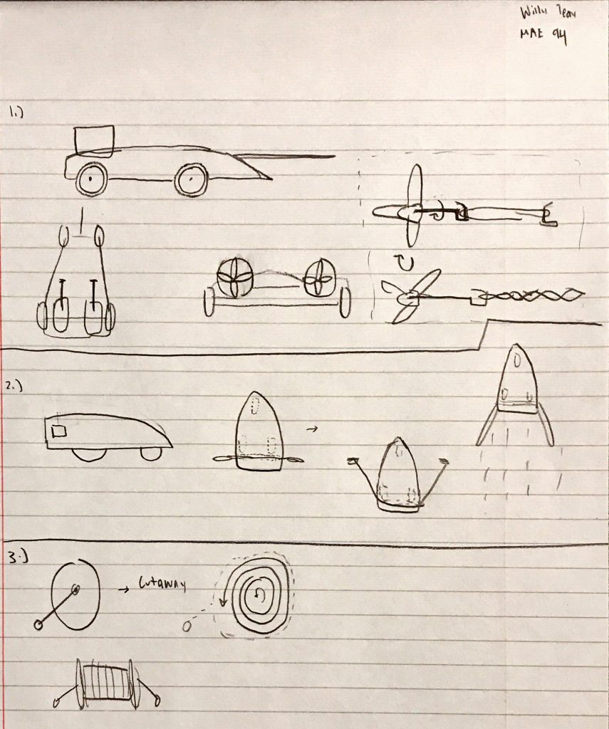
My initial design was very stylish and took inspiration from the F-117 Nighthawk. Unlike the F-117, this design truly was a hopeless diamond. This design has a lot of unnecessary mass and the propellers were too small to provide enough thrust.

The next iteration of the design focused on reducing weight and adding a larger propeller.

Some FEA was conducted on the rubber band hooks and that forced me to reduce the stress (as it went above the yield strength for PLA) by filleting the corner and by enlargening the piece diameter.

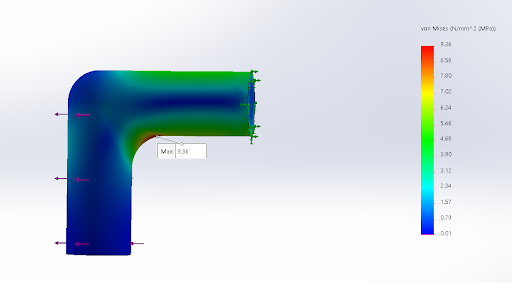
The changes made the project seem like a lost cause. Another FEA analysis implied that the vehicle will bend due to the load of the rubber bands, which would be a severe handicap to its ability to move. It is entirely possible that the deformations are actually negligible since I wasn’t aware that SolidWorks by default doesn’t use a 1:1 scale, but instead exaggerates the deformations to allow for better visualization.

A final CFD analysis on the propeller confirmed that I would not get enough thrust to propel the vehicle.

On the fly, I created a new design. This time, it will try to use Newton’s Third Law of motion to propel itself. It is similar to clicking a pen on a desk and having it eject, except that instead of using springs, we’ll use rubber bands.

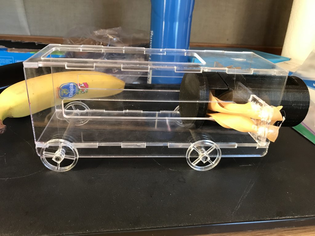
Suddenly, I had to make another design change. The 3D printing services were getting bogged down, so I converted as much of my model as possible to be manufactured out of laser-cut acrylic.

After a lot of sanding and gluing, I had a finished product.
Additionally for this class, I used LaTeX to make an excessively detailed lab report that is available for viewing here:
MAE 150B
This is an aerodynamics course offered at UCLA. It is not a project-based class, but it does contain a small CFD (computational fluid dynamics) project that I found fun. Due to honor code reasons, I will not be uploading my final report, but I will give a quick spiel and share some cool images.
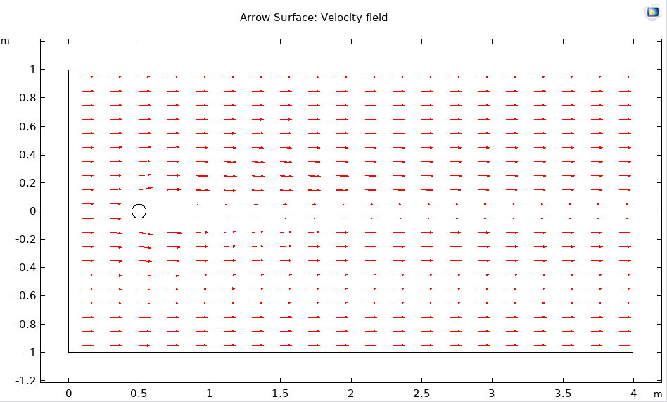
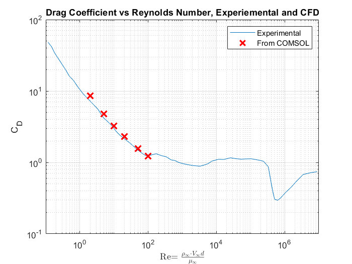
The basis of this project is to conduct basic CFD on popular models such as a cylinder or standard airfoils. The class used COMSOL multiphysics for the CFD due to its user-friendly interface. All of the simulations were done in 2D. There was a 3D portion, but it was optional due to limitations with processing.
For the flow over a cylinder model, velocity was varied and the results from the CFD were checked against results obtained from a physical experiment.
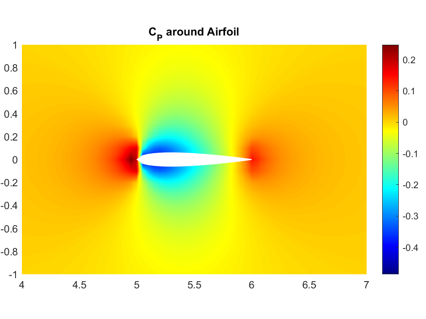
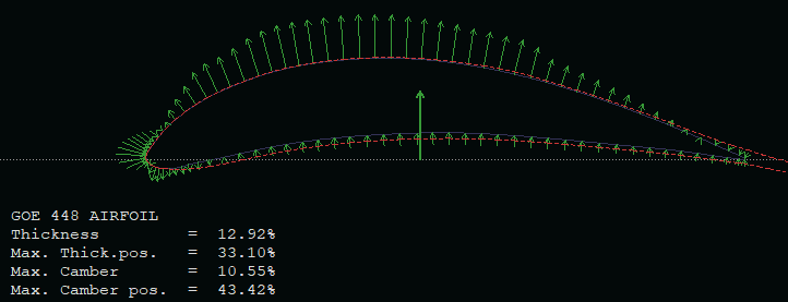
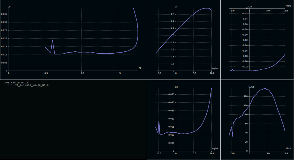
CFD was performed on a symmetric (NACA 0010) and a cambered (NACA 4410) airfoil. In each of these cases, we varied the angle of attack and compared the results to each other and to thin airfoil theory.

This class also featured a homework assignment where we had to create our own CFD code by using an approximation method called the panel method. I had the pleasure of introducing inefficiencies to my code which caused the run-time to be 3 hours long for a pretty simple scenario. I was really happy with the visual result of this homework assignment.
If you are interested in seeing some of the guts that went into some of the visuals that were shared or my full reports, feel free to reach out to me as long as you are not going to use it to cheat on this course.
MAE 157A
This course is the capstone course for aerospace engineering majors. I took this course a year early because I took the necessary pre-requisite courses and I wanted to take the mechanical engineering capstone course during my final year.
This course is focused on rocketry and I worked in a group with 5 other aerospace engineering students to design a rocket that can reach 30,000 feet with a 10 lb payload. My role in this group was a vehicle engineer, and I contributed heavily to the CAD of the rocket. This course can be divided into a group-work component and a homework component. I liked the homework in this course more than any other because of how engaging it was.
Homework
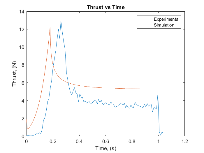
Due to the Covid-19 pandemic, the homework assignments changed from lab work (such as doing tensile tests, manufacturing a composite part, etc) to simulation-oriented work (such as making a trajectory code, CFD, FEA, etc). This section will show some figures generated for the homework assignments. Contact me if you are interested in seeing some full reports.


Although the pandemic forced me to miss out on valuable hands-on experiences, particularly with composite layups/curing, I am still glad that I got so much exposure to simulation-based engineering.
Group Project
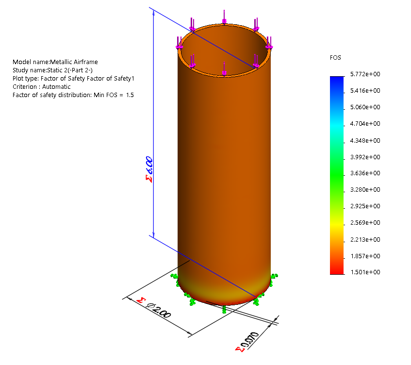
I was the lone junior in my group full of seniors. I was fortunate to have been placed with such a competent and talented group. To be honest, I was probably one of the more forgettable members of my group. Most of my work was creating the CAD models for a large part of the rocket and the overall assembly. I also helped do a chunk of the finite-element analysis and a ballpark simulation using OpenRocket
I am most proud of utilizing a SolidWorks Design Study to optimize the design of the bulkheads. I parameterized the model and coupled it with a simulation to find a bulkhead that meets the strength requirements for the minimum weight.
I have attached a copy of my group’s final report. I want to reiterate that most of this report is not my work. See page 85 to see what sections I wrote and contributed to. If there are any issues with sharing a copy of this report, please let me know immediately and I will get it fixed.
MAE M168
This course is meant to serve as an introduction to finite element analysis. The course dives deep into the mathematics behind FEA and allowed us to be exposed to ABAQUS.
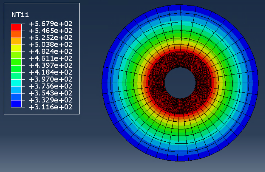
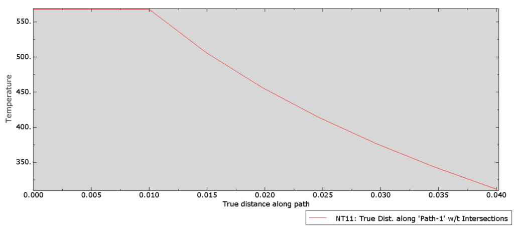
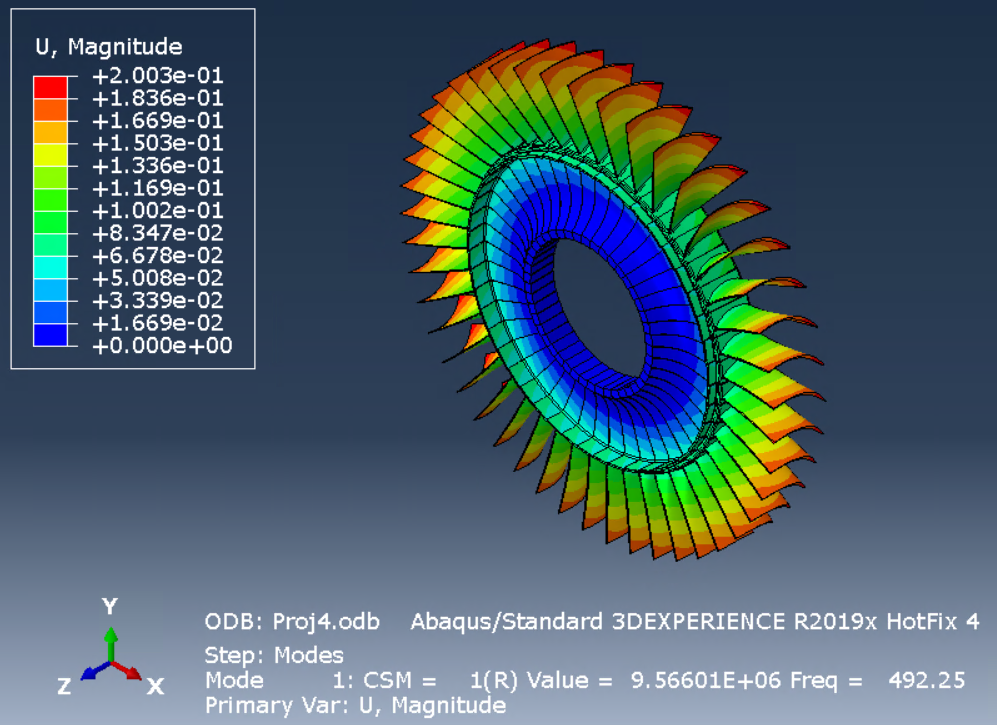
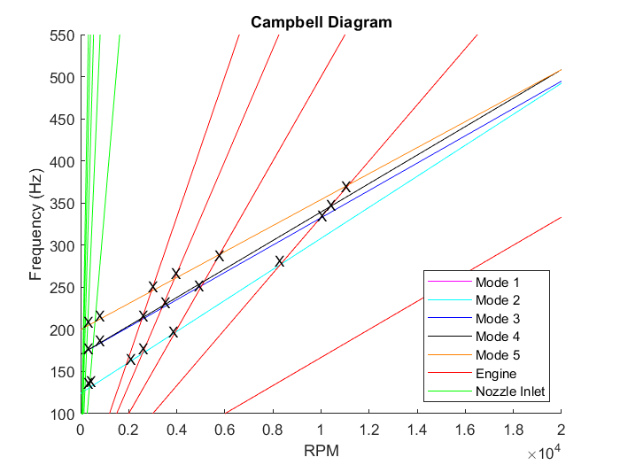

One thing I really liked about this class was the breadth of the topics covered. Some of the topics we went over included statics, heat transfer, buckling analysis, and modal analysis. The projects were both fun, but also overwhelming. These pretty pictures are very satisfying once the amount of hard work that got put into generating them is factored in.
The less glamorous side of this course involved a lot of differential equations and large matrices.
MAE 166C
This is a course about the design of composite structures. It was mostly theory and allowed me to get exposed to cool things like classical laminate theory and failure models (Tsai-Wu and Tsai-Hill). The homework assignments were fun and an excellent excuse to excessively use MATLAB.
The final project for this course was to design a composite structure that can withstand a distributed load while cantilevered. This project was very rewarding for me because it was the first time that I played with a slightly sophisticated optimization process (Monte-Carlo).
Below is an attachment of the final project report
MAE 154A
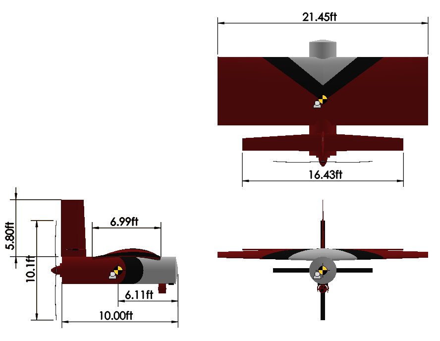
This course was one that I was very excited to take. MAE 154A goes over the preliminary design of aircraft. This course was essentially a ten-week project where the goal was to design a plane to complete a custom mission that we make up. Our mission was to survey the Angeles National Forest for small fires in order to prevent them from growing into catastrophic wild fires. The project was done in small teams of ~4 students.
My biggest contributions to this project were choosing the airfoil using XFLR5, finding stability coefficients using DATCOM, and making the CAD model with SolidWorks. I contributed less to the autopilot design, mission planning, and parameter optimization.
Optimization
Even though I did not contribute to the meatiest parts of the optimization code, I do understand how it works. I played a role in general proofreading/brainstorming and coding the weight estimation loop. The weight estimation code takes a guess weight and plugs it into a series of empirical equations. This new weight is plugged back into the equations until the value converges. The empirical equations are driven by aircraft parameters
The main optimization code is a Monte Carlo algorithm that varies the various aircraft parameters such as engine, airfoil (see next section), wing aspect ratio, incidence angles, etc. The aircraft generated by these parameters were tested against several failure criteria. These failure modes were very involved and took up a lot of our time. A design fails if it cannot achieve the desired performance to complete our mission. This can mean lacking endurance, turn radius, rate of climb, etc.
After running the algorithm, we updated it by using the results to help narrow down the ranges that each parameter has.
Airfoil Selection
I started the airfoil selection process by choosing a handful of airfoils that had very good lift over drag (CL/CD) ratios from airfoiltools.com. This selection excluded wind turbine blades but included some popular airfoils that were not known for their performance. I heavily utilized XFLR5 to do most of the analysis and exported the data to become inputs for our optimization script. The data required some cleaning and had several more coefficients that needed to be calculated using Excel.
Stability Coefficients
The stability coefficients were the hardest part of the project for me. I had to scour through a bunch of literature to code the correct equations into MATLAB. However, that wasn’t enough, and I went on to learn how to use DATCOM, which is written in the archaic language of FORTRAN. Getting the program to work on my computer was a nightmare in of itself. Nothing pretty really came out of this, it was just a lot of crunching numbers and ugly math.
CAD
After we finalized our design, I pulled one or two all-nighters to get all the parameters into CAD. This includes non-trivial modeling such as importing the chosen airfoil coordinates before correctly scaling, positioning, and adding the dihedral to the wings.
I honestly thought that the plane was a bit ugly, and it gave me Gee Bee vibes. However, I am very proud of how hard our entire team worked to get to this point.
Report
Our report can be accessed here:
I personally think that we could’ve done better collectively because of how crunched for time we were towards the end of the course. I am a bit bothered by how the final design looks geometrically, but there was no time left to revise the design by the time we reached this stage. Honestly, I came into the class expecting to be very proud of the final product. I want to emphasize that I still had a great time in this course and was fortunate to be a part of a pretty good team.
Maybe this course can benefit from being a two-quarter course like MAE 162D/E.
MAE 162 D/E
MAE 162D and MAE 162E are the two classes that compose the mechanical engineering capstone that spans the Winter and Spring quarters. This class has a group project as well as homework/lab assignments.
I am the first (if not only) student who has taken this course without majoring in mechanical engineering. It took precise planning for me to squeeze the additional upper-division classes into my schedule to fulfill the required coursework. I actually got rejected from taking this course after going through several layers of departmental administration. Fortunately, I had a good relationship with one of the professors who teaches these courses.
I took this course during the COVID-19 pandemic, meaning that everything was virtual. Typically, we would’ve actually built our designs and physically compete with them, but the course was restructured to be more simulation/design heavy. As a result, the class leaned more heavily on SolidWorks and MATLAB than it would’ve in prior years.
Homework Assignments
This course was well structured because the homework assignments tied in very well to the group project. This section will highlight a few selected assignments
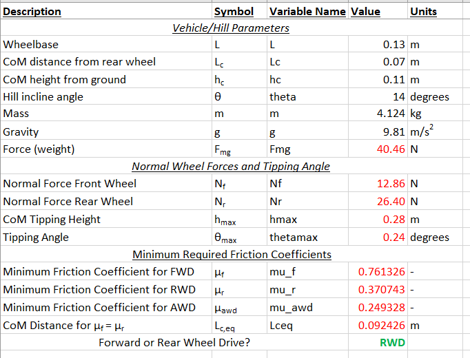
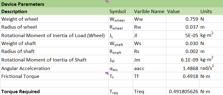
A handful of our assignments involved using Excel as a calculator. In this example, we used our calculations to determine whether a rear or forward wheel drive is optimal for a vehicle climbing a hill.
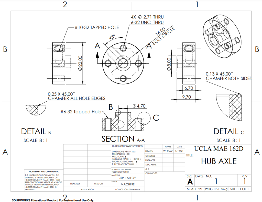
We were also given the opportunity to practice producing engineering drawings from CAD models
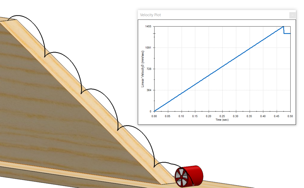
One of the coolest things I learned from this course was how to use SolidWorks motion studies. This essentially allows us to analyze the kinematics of moving parts such as linkages and wheels. Motion studies empower us to evaluate the displacements, velocities, accelerations, torques, etc. of these moving systems

We also used motion studies to animate mechanisms such as gears meshing and a rack and pinion.
We were tasked to use Simulink to simulate parts of the obstacle course. The meat and potatoes of this were getting contacts to work correctly. Some of the challenging parts included getting the gears to properly work on the sample vehicle and fine-tuning the parameters (starting position, motor speeds, etc) that allowed the vehicle to successfully climb the hill without stalling, veering off, or overshooting.
Group Project
The group project was to design a robot to conquer an obstacle course created by the professor. Additional constraints were given to use such as a starting bounding box, not being able to leave any parts behind, etc.

One of the first steps of designing this robot was to size the motors. The motor sizing is driven by the ability to complete the course in a timely manner and climb the hill at the end. A lot of this work can be branched off from the homework and lab assignments. Once we had a required torque, we were able to find motors from online vendors
This was a group project, and I was very fortunate to be in an excellent one. My teammates were hard-working, in sync, and responsible. They really deserve a shout-out for how well they worked. I had a really good time in this course, and my teammates were a big reason why.