Contents
Introduction
BattleBots, sometimes known as “Combat Robotics” is a hobby that involves building remote-control robots to hit one-another until something breaks.
Me and BattleBots
I feel like it would be appropriate for me to preface this page by saying that I am such a huge fan of BattleBots. It’s something that I whole-heartedly enjoy watching, reading about, and learning about. It is something that I grew a passion for; one of the reasons why I decided to pursue engineering is BattleBots.
“DrumBot”, 3-lb BattleBot
I was fortunate enough to have a BattleBot program at my school. During my freshman year, I joined ASME solely to participate in BattleBots. When I joined, new members had two options of what to build. There was a shell-spinner that focused on machining and manufacturing, and then there was a drum-spinner that focused on design and CAD.
I joined the latter and was put into a team of three with then-strangers. Our task was to use SolidWorks to design the chassis for a drum-spinner. The project leads already sorted out all the electronics and the weapon for us new members. However, at that time, none of us were proficient in SolidWorks, so this simple task took many months.
We would often meet as a team late at night and work on designing the chassis. This is an almost-final model. The only differences were that an acrylic top plate was used instead of a 3D-printed one and that we were not able to cover the aluminum bar with steel.
After designing the robot, we had to lathe a large aluminum cylinder down to shape, bore out a hole to press-fit the motor, and mill flat edges to complete the weapon. We then had to assemble the robot electronically.
My team was the only beginner team that completed in time for RoboGames 2017 that year.
Robogames 2017
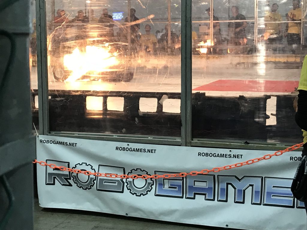
I was the only freshman to embark on the epic road trip from LA up to Pleasonton. It was definitely an experience, to say the least. I remember sitting in the parking lot, learning that my robot got named “Drumbot” because nobody in our team made up a name. Everybody else, including my project leads, was busy working on the 60-lb flagship BattleBot, while I just had a table with my three-pound bot.
My table was neighboring one manned by Paul Ventimiglia and Marc DeVidts, builders of BiteForce (BattleBots Season ‘1’ Champion) and BiteForce respectively, so I was star struck. I walked around the pits and got to see so many robots up close. One of the most menacing robots in the entire vicinity was Touro, of team RioBotz. They literally wrote the book on Robot Combat. Little did I know, I was going to fight them.
Team Riobotz brought along a 3-lb BattleBot also, and luckily for them, they got to fight me. Seconds after the fight began, I lost drive on my left motor, meaning that I could only pivot around. I spun up the weapon and positioned the robot to face Min-Touro, but their weapon spun faster than mine, allowing them to get an uppercut. My robot landed upside-down and was not able to drive properly because we did not have wedglets or skids on our top. This caused our weapon to constantly be in contact with the floor. In what was probably a mistake, I said: “Keep going!”. The Brazilians did and my robot got trashed, but it was AWESOME. The driver later said to me, “Sorry about your robot,” and one of my team leads then told me, “You know you could’ve tapped out, right?” Oh well, it was worth it.
Horizontal Bar Spinner
After RoboGames, I joined a new team and worked on the design of a horizontal spinner. The team consisted of three freshman (including me) and two juniors. While the juniors mostly dealt with the electronics, us freshman worked on the mechanical design. We used 6061 for the top plate, bottom plate, backplate, and weapon bar. We also added two steel teeth to the weapon bar. The motor was pressed into the weapon, just like the beginner designs.
Looking back at this design, its biggest flaw would be that it would exceed the weight limit of three pounds. The CAD model weighs exactly three pounds, and once fasteners and wiring are added, the completed robot would certainly be overweight.
We finished the CAD model at the end of my freshman year, but never manufactured the design.
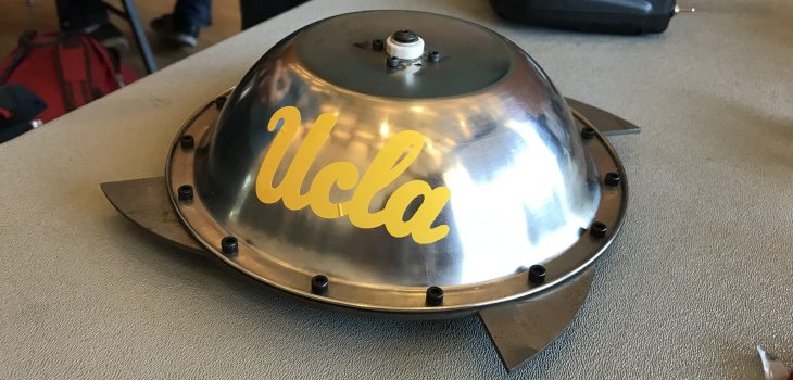
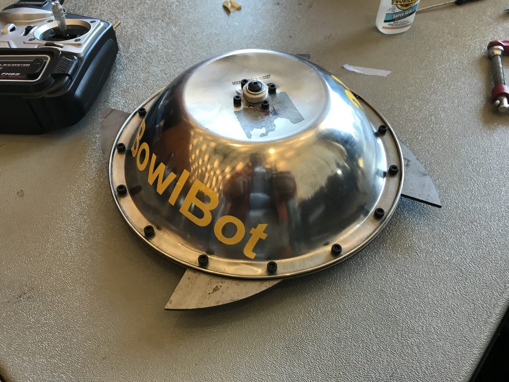
“Bowlter” – 3lb Shell Spinner
At the start of my sophomore year, I joined yet another BattleBot team. This time, the team consisted of five members, with all but one a sophomore.
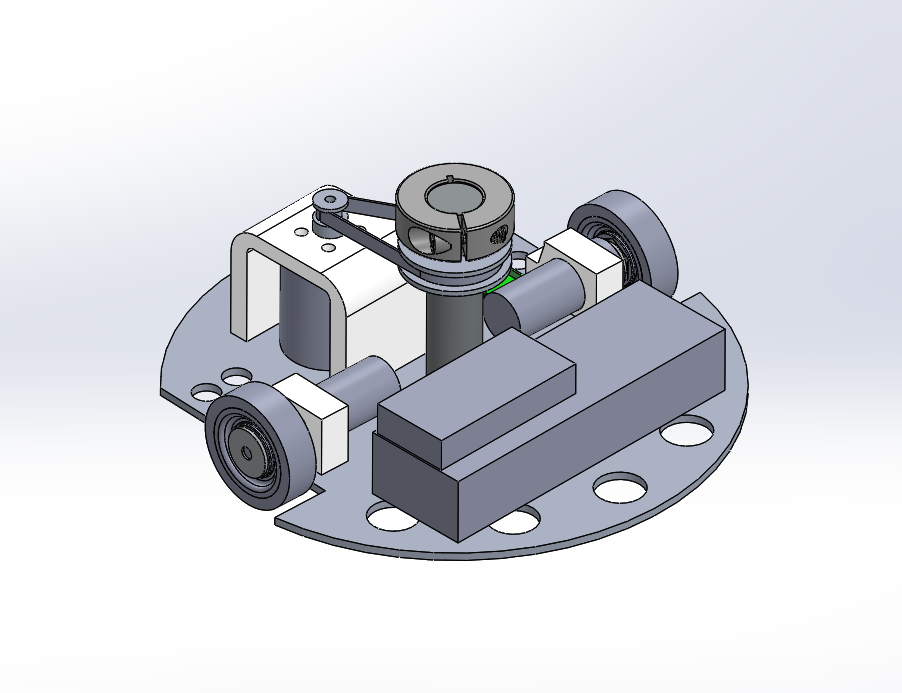
Admittedly, a majority of this robot’s design was a derivation of the shell spinner from the previous year. The electronics and shaft were nearly identical, but the baseplate was modified and the pulleys were custom made.
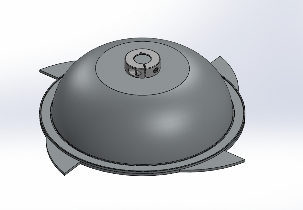
A stainless steel bowl purchased off of Amazon served as the shell for our spinner. Next, we added a ring of steel teeth as an impactor.
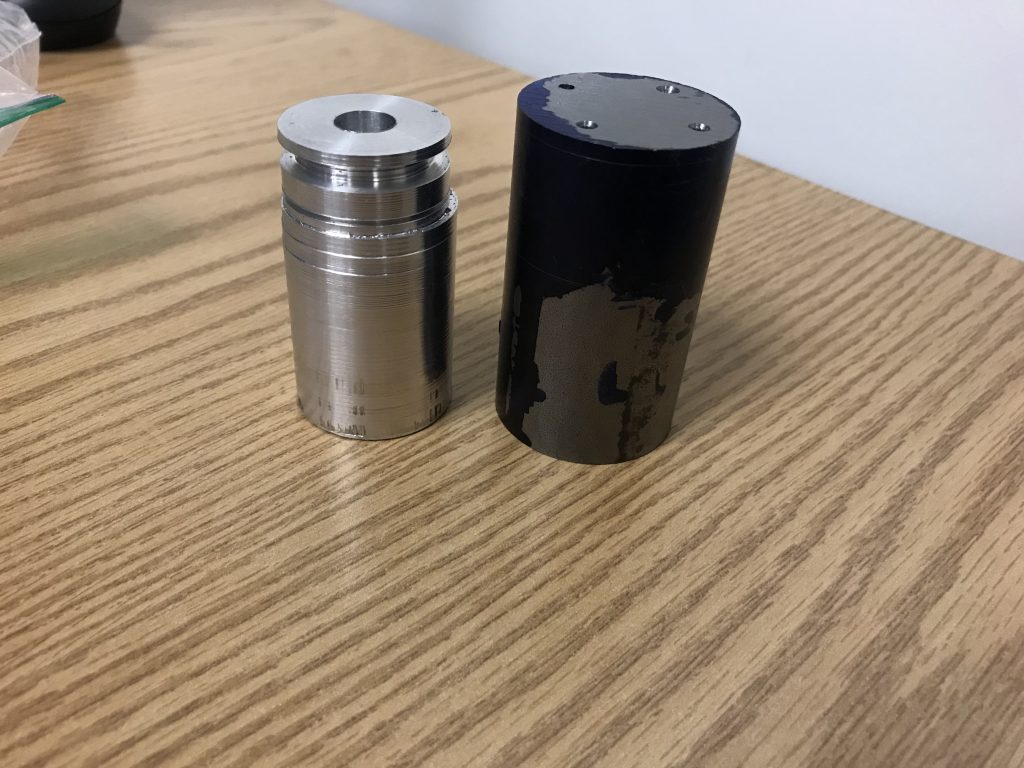
We turned a pulley from round aluminum stock and cut it off with a cutoff tool, all on a small lathe. The chunk of steel to the right was supposed to become the shaft. However, the stock we purchased did not have enough extra room to held in the lathe’s jaws, so we took a previously made part. Additionally, one of the biggest mistakes I made in this build was eyeballing the mounting holes on the pulley.
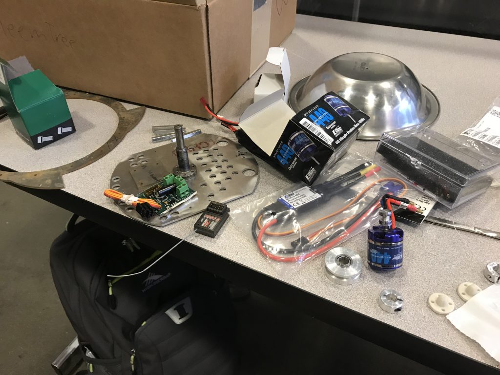
We used the same 40A ESC and 4200KV Brushless motor from the last year.
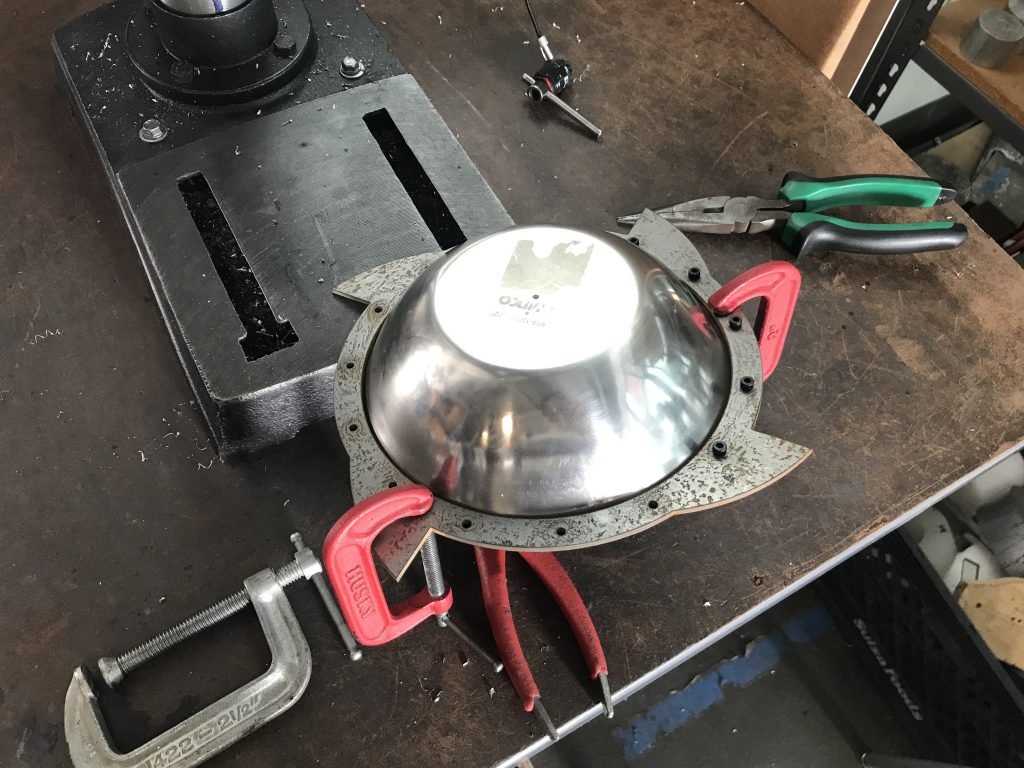
The steel ring was cut using a waterjet. We then match-drilled the holes onto a lip on the bowl and fastened it with 15 M3 screws and nuts.
We used laser-cut acrylic to make a motor mounting plate. Additionally, we used 3D-printing to make mounts for our drive motors and for skids to keep the robot level. The electronics featured several XT-60 connectors and lots of zip ties and electrical tape.
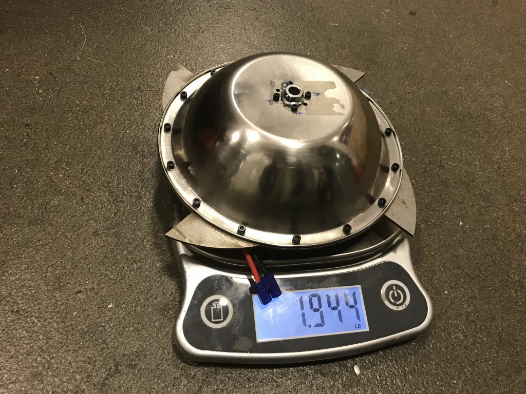
In the end, our robot was very underweight, but the diameter of the bowl did not allow us to install larger and more reliable motors.
Because RoboGames ceased operations, the robot competed in the newly formed Cal Combat Robotics Competition at UC Berkeley. The robot lost to an egg-beater spinner.
2018-2019 Flagship BattleBot
Throughout the entire school year, I was a part of two BattleBots teams. This second team was the Flagship team, which had some of the brightest students I have known.
The team’s plans for the 2018-2019 year was to create a 60-lb flipper, similar to the British flippers from Robot Wars. Throughout the year, I was mostly a sponge, soaking information and learning from my peers. However, I did contribute by introducing GrabCAD Workbench as a better way for the team to collaborate on CAD files and helped make CAD models for various electronic components.
Unfortunately, the team did not end up completing the robot because RoboGames was canceled.
Flamethrower Wedge – Summer Project
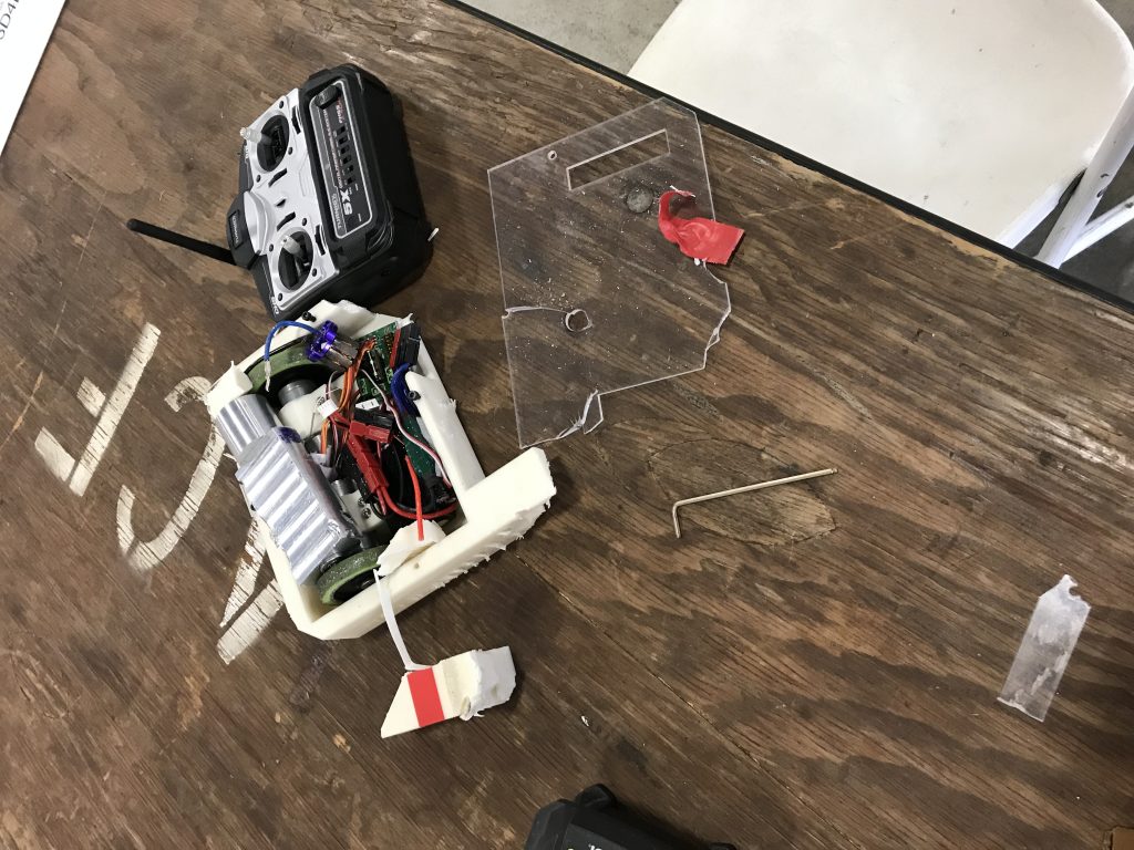
During the summer of 2019, I wanted to make my own BattleBot to challenge myself. I decided that it would be best to play it safe and make something that did not have a spinning weapon. However, I did not want to make a boring wedge robot, as the community frowns upon it. I decided to make a flamethrower.
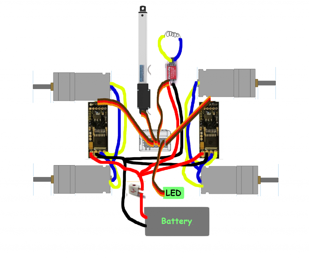
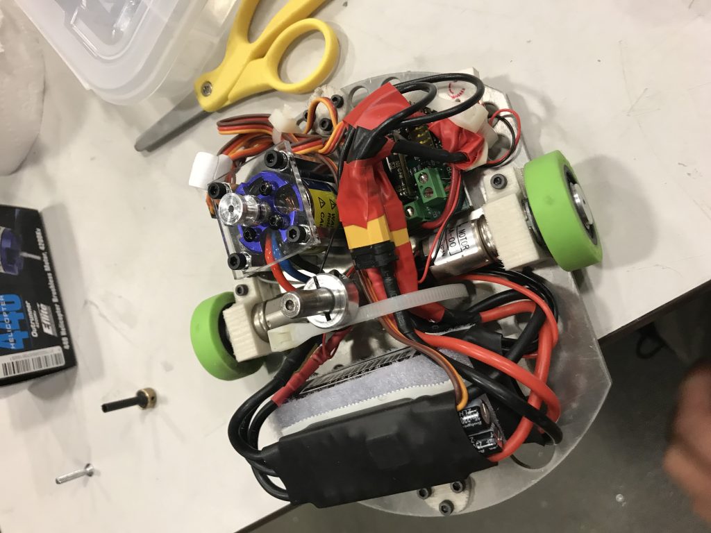
This project helped me learn a lot about electronics, from deciphering LiPo battery numbers to how an RC system works. My design is a four-wheel-drive push-bot with a flamethrower attachment. This robot was inspired by heavyweights such as Raging Scottsman and Sewer Snake. The flamethrower uses a linear servo to push a fixed butane canister, which sprays butane onto a coil of kanthal wire that a speed controller heats up. However, I was notified through Facebook that most events prohibit the use of flame weapons.
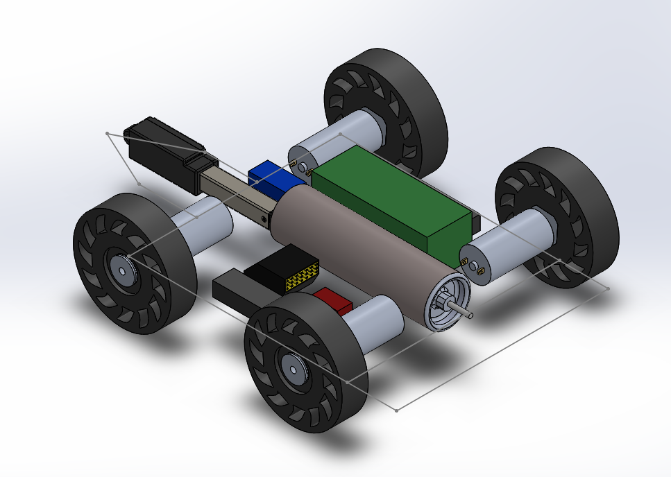
To make matters worse, my initial CAD design took up more space than I predicted, meaning that there wasn’t enough weight to accommodate a chassis. My first plan was to make a one-piece UHMW chassis, as it is very impact resistant and relatively light. I looked using thin aluminum plates instead to save weight, but it was looking pretty dire, especially with the motor and wheel setup that I purchased.
Vertical Spinner – Summer Project
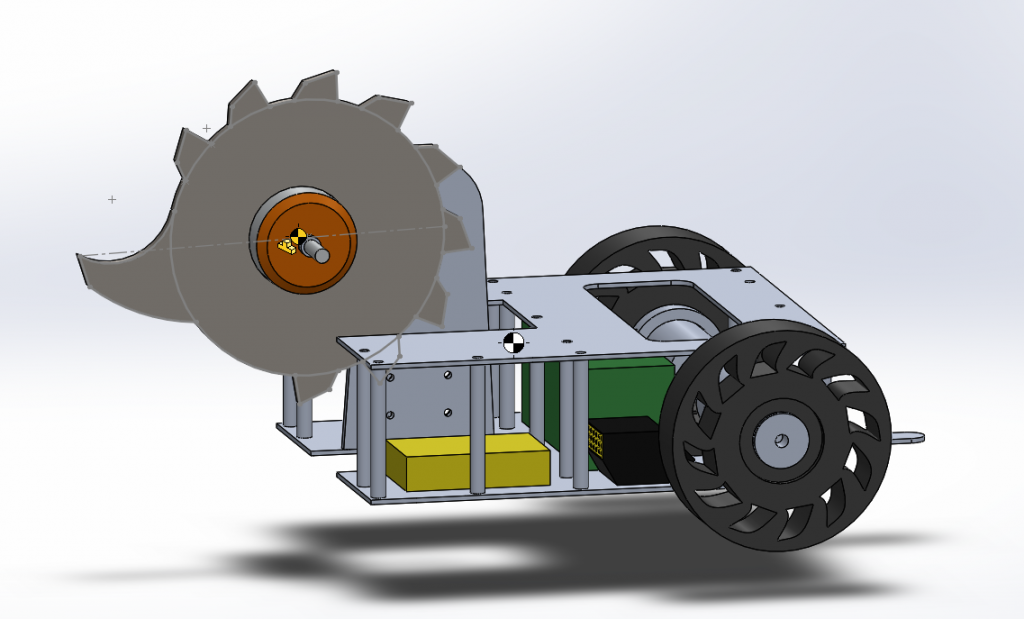
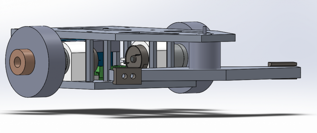
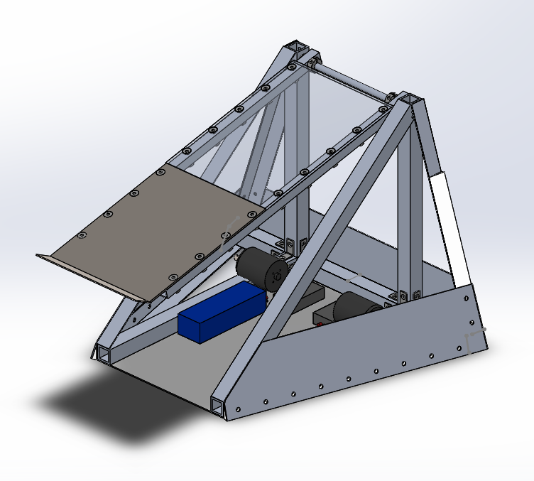
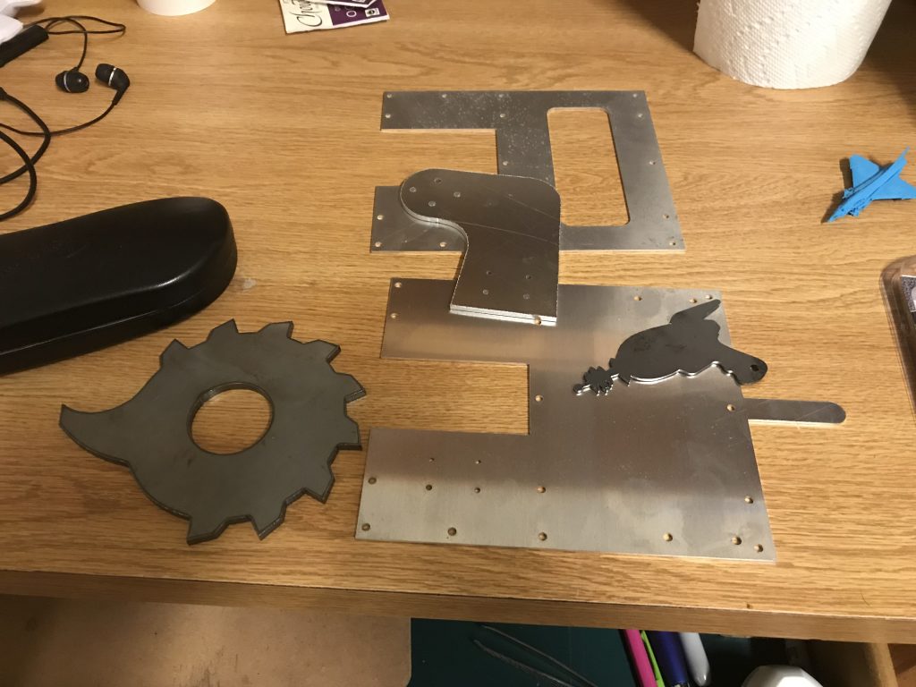
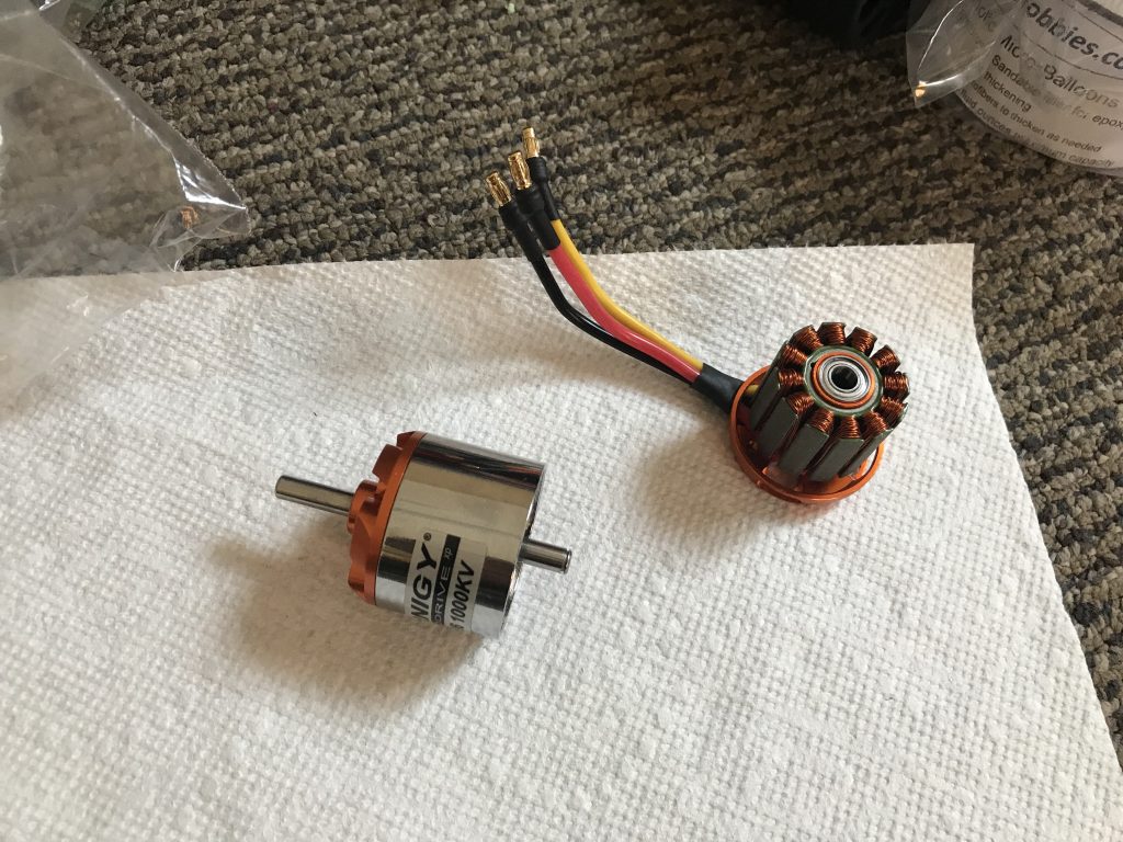
Since I already purchased components, I was in the mindset of “in too deep to give up,” so I decided that I would make a vertical spinner. This robot (especially the blade) drew inspirations from Cobalt, a vertical spinner that competed in the BattleBots 2019 TV Season. I am pretty excited about this BattleBot, but I think that it’s going to explode once it touches something. I designed this robot to be economic and easy to construct in a home devoid of power tools and machining equipment.
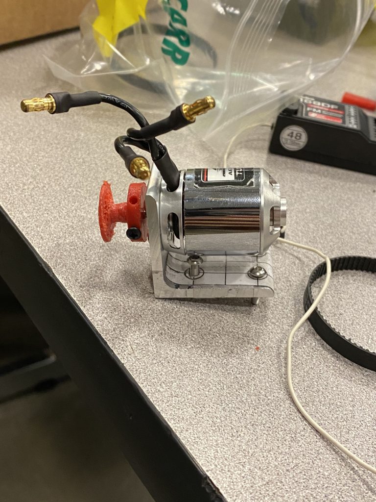
The weapon for this BattleBot is more than half a pound of quarter-inch-thick hot-rolled steel. A Turnigy D3542 1000KV brushless motor powers the weapon. Unfortunately, due to budget and machining issues, this design was not able to include a pulley, meaning that my weapon motor will suffer from any direct impact. I plan to battle harden the motor by adding epoxy around the magnets of the motor.
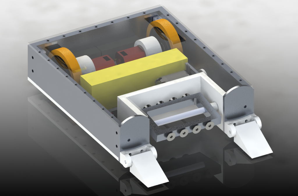
Dancing with the three-pound weight restriction led to some other sacrifices, including a thinner aluminum weapon arm and the loss of motor clamps. I had to reduce the thickness of the weapon arm to save weight. Hopefully, the 6061 alloy is ductile enough to not snap upon impact. I originally secured the weapon to the motor using motor clamps, but I had to remove them to save weight. The motor clamps I found online were too thick and heavy to use. I slightly oversized the weapon’s hole, and am planning to secure it to the motor using various adhesives.
I designed the BattleBot to lean forwards so it can deliver a nice uppercut. Defensively, there is nothing to write home about, asides from a little peninsula on the backside that should make it harder to tip backward.
This “Summer” Project lasted past the summer. It was hard to find motivation when my priorities were shifted. This project stretched into the school year, where I had to prioritize working on other obligations including another Battlebot.
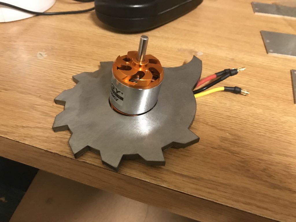
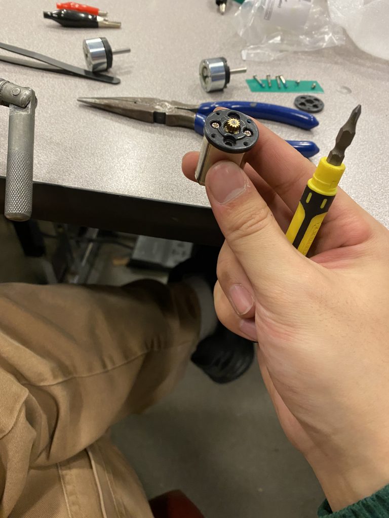
I decided to slightly oversize the weapon’s hole to make sure that the motor fits because I do not have the capability to grind out steel, and if I did, it would be difficult for me to get a perfect circle. The plan is to fill the gap with a mixture of epoxy and playdough.
Preparing to “battle-harden” the weapon motor was a pain. Removing the circlip was excruciating
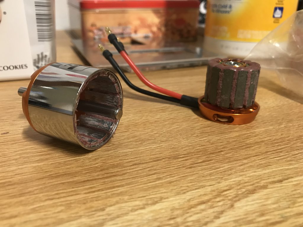
Battle-hardening a motor is essentially adding epoxy and a thickening agent to make it as hard as possible for the magnets of the brushless motor to come loose.
Right now, this particular robot is on hold. I think that a more secure method is required to attach the motor to the weapon. Additionally, I found some more compact drive motors and a more compact ESC for the weapon.
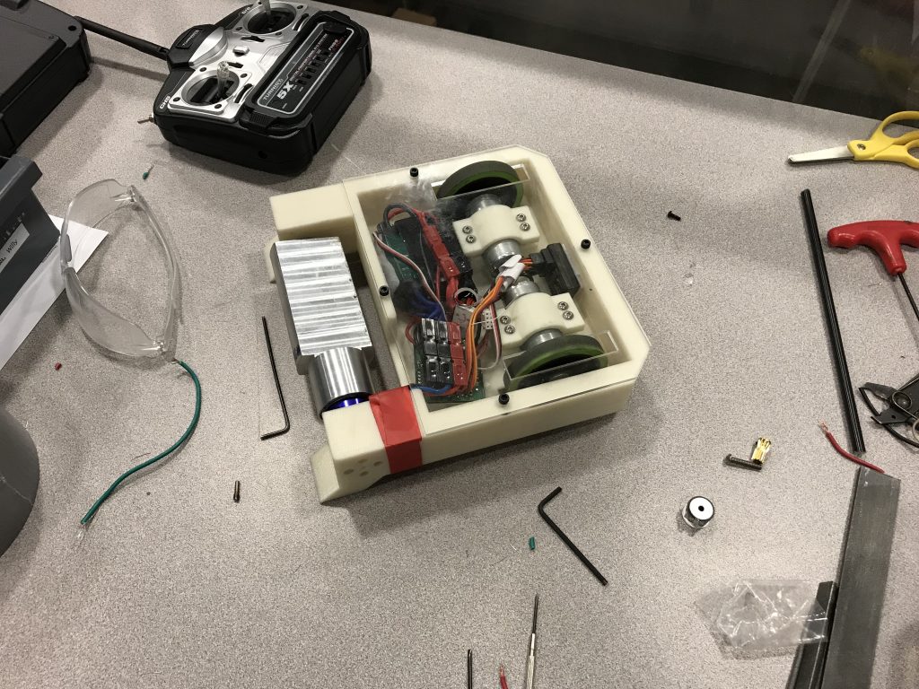
2019-2020 Flagship 3-lb Egg-Beater
During my junior year of college, the flagship program got restructured. Instead of being on one large team, flagship members were separated into 3 smaller teams. I was a part of a team that will build a 3-lb Egg-Beater (meaning the weapon is a rotating part that somewhat resembles an egg beater). The difference between the flagship 3-pounders and the regular 3-pounders is that we have a larger budget and more freedom over component choice.
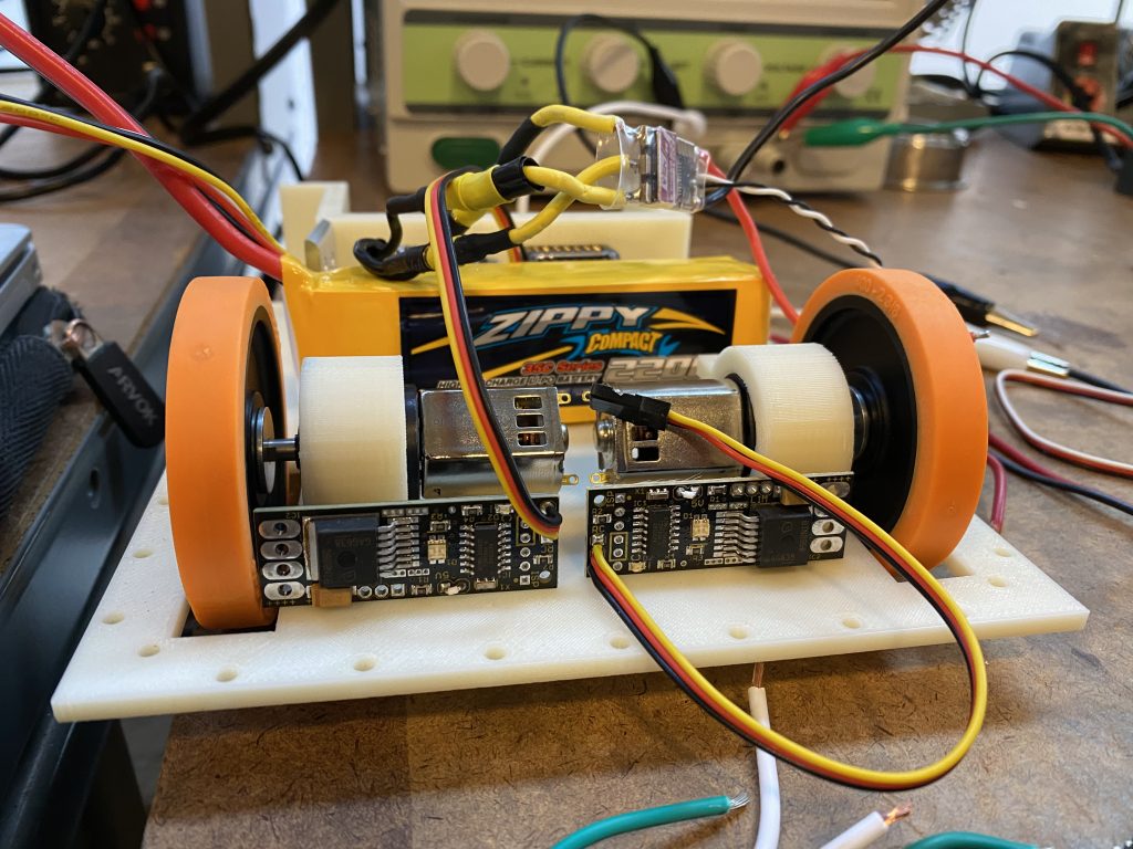
I chose all of the electronic components for the robot, which was an interesting experience. Right from the get-go, I knew that I wanted to use the Neo-Rhino motors. These motors were originally designed for modifying nerf guns, but have been gaining a reputation as a powerful, compact, and reliable drive motor choice for three-pound robots.
During this time, all the other robots at UCLA were switching to brushless drive. This process is described in more detail in Robert Cowan’s YouTube Video, but essentially it is separating a brushed motor from its gearbox and replacing it with a brushless motor. The benefits of doing this are that one can save some weight and improve drive power/efficiency. The downsides of using a brushless drive system are that it requires more work to assemble. Not only do you have to remove the pinion gear from the brushed motor and mate it to the brushless motor, but you also need to find a compatible ESC (running BLHeli or SimonK firmware) and program it so that the motor can spin in both directions.
The Neo-Rhino motors that my team used still required a painful pinion removal and transplant, but it was simpler to wire electronically. I chose to use Wasp ESCs because it is able to handle the burst current of the Neo-Rhino motors. This means that in a shoving match or if the robot gets stuck, the ESC will not burn out.
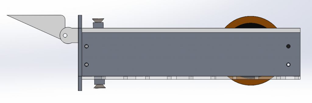
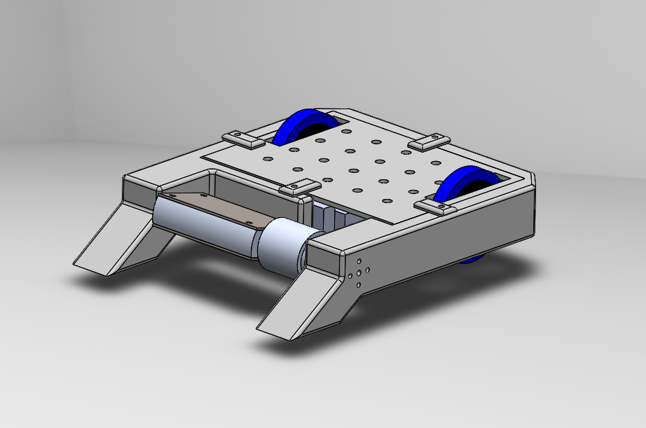
The chassis of the robot had a 3D-printed floor, aluminum sidewalls, and an acrylic top piece. The front of the robot has a piece of tall armor and a 3D-printed wedge. The tall armor was designed so that if the robot gets flipped, the weapon will still be able to spin without hitting the ground.
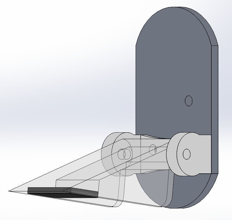
The wedges are designed to be fastened to the robot with a hinge so that it would be flat on the ground. Additionally, the wedges had a small recess placed in them for a magnetic strip. The intent of these features is to win the battle for ground clearance. Usually, the robot that is lower to the ground has an advantage because it is able to get under its opponent and deliver an ‘uppercut.’
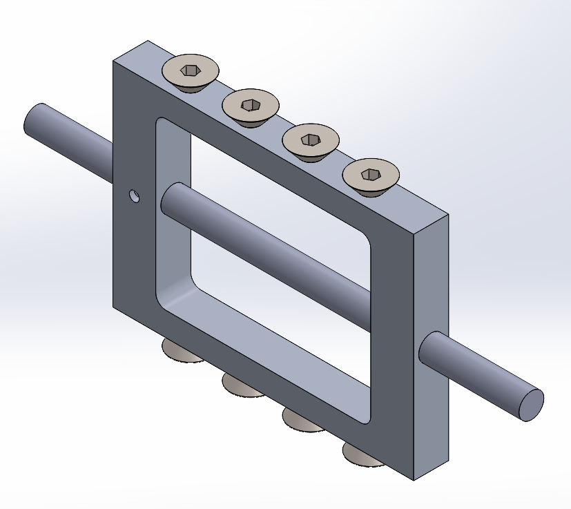
The weapon is an egg-beater. It is an aluminum bar with a hole in the middle, and steel countersunk screws as impactors. The steel impactors allow the weapon to cut other robots. Regular aluminum is too soft to be an effective weapon.
The weapon is powered by a Turnigy Aerodrive SK3 2836 1500 KV motor. Some considerations that I took into account when choosing this motor was its KV, power output (watts) , and size. Using the RioBotz Combot Turotial, I choose the weapon’s RPM to be 9000. I knew that the robot will be operating on a 3S (~11.1 V) system so I can multiply that by the motor’s KV to determine the motor RPM, and then I can check to see the diameter ratio of the two pulleys.
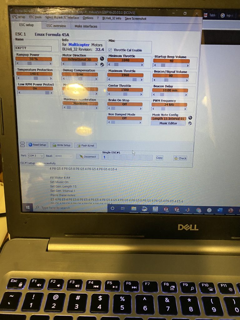
To make my robot unique, I wanted its weapon to be bi-directional. I have not seen this feature implemented in other robots. This led me to use this T-Motor F45A ESC, which operates on BLHeli_32. This allows the motor to have a bi-directional and lets it play a startup tune.
One large risk that my team took (probably out of collective laziness) was to 3D-print our pulleys instead of lathing a metal part. The pulleys were fastened using self-tapping screws designed for plastic. While this did save a lot of manufacturing time, the finished result looked very fragile.
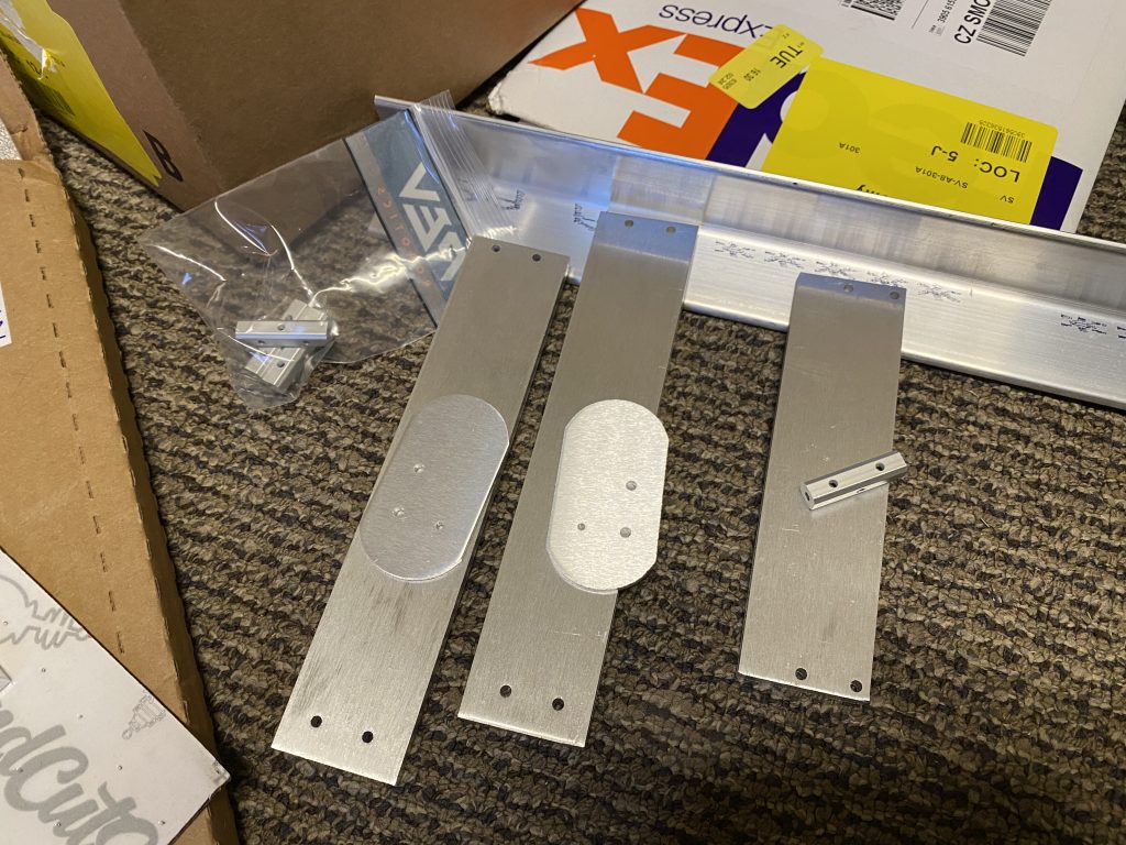
One of the most stressful moments for me during the process of creating this robot was outsourcing all the metal parts (except for screws and weapon shaft) to be manufactured with SendCutSend. Don’t get me wrong, I absolutely love SendCutSend, and I would highly recommend their services. However, when making a large order (complete with spares), I mistakenly inputted the wrong thickness (.125″ instead of .25″). This was a completely avoidable mistake and it happened due to my carelessness. It was one of my biggest screw-ups of the year and cost me a lot of money out-of-pocket.
During the last two or so weeks of the winter quarter, disaster struck. The SARS-CoV-2 virus made landfall on the states and started to rapidly spread. Due to public health concerns, the competition that the robot was designed for was canceled, and soon I found myself home indefinitely as campus shut down.
At the time, this hit me really hard. I felt miserable and extremely frustrated that all the effort I put into this robot never fully materialized. It took me a while to realize that I wasn’t the only person in this position and that there are millions of students all over the world who had to abruptly stop whatever they were doing, from theater productions to engineering competitions.
2020-2021 Flagship 15-lb Horizontal Spinner
For my senior year of college and my fourth year of involvement with collegiate combat robotics, I will be helping with the design and construction of a 15-lb horizontal spinner.
Melty Brain…sometime soon
One of my future plans is to build a melty brain. A melty brain is a robot that uses its drive motors to spin the entire robot. While the entire robot is spinning, an accelerometer and a processor allow the robot to be driven as if it was a traditional robot. This allows for almost the entirety of the robot’s mass to be used as a weapon.
I was planning to do this during the summer of 2020, but I ran into time and motivation issues. My vision is to create a spinning titanium blade that is hydro-dipped in a wood pattern for the 3lb weight class. The electronics would then be secured in a fiberglass or 3D-printed shell, and the robot will be running off an open-source melty brain code called Open Melt.