Throughout my time with UAS at UCLA, I have mainly worked with payload/deployment (i.e. dropping things) systems. For the 2019-2020 school year, I took on a role as an Airframe Lead.
Contents
2017-2018 Year
For the first part of my freshman year, my contributions were minor as I was still getting up to speed with SolidWorks and manufacturing methods.
One of my first contributions was drilling some holes for the baseplate.
Finally, once I started to get the hang of things, I was delegated to design the payload drop system.

I designed this device for the 2017-2018 AUVSI SUAS Competition. This purpose of this mechanism was to drop the payload, an 8-oz water bottle, onto the target. In this device, a servo pulls a pushrod slightly out of a wooden block so that a zip-tie that is attached to a foam capsule that contains the payload would be released. A tube made from a 2-liter soda bottle prevents the payload from swaying during flight, and a streamer attached to the foam capsule helps the payload stay on course when it is released.
Initially, the team did not catch a subtle rule change from the previous year. Last time, the 8-oz bottle was supposed to remain intact during the drop, but now the bottle was supposed to break and release water to simulate a fire-fighting situation.
In response to the updated rules, I revised the design by removing the protective foam. A skirt of razer blades replaced the foam capsule, intending to puncture the water bottle when the payload reaches the ground. Thin strips of cardboard suspend the razer blades and are designed to structurally fail upon impact.
After dropping a water bottle off the roof of the engineering building, it was determined that razers were not necessary.
The availability of 3D-printing caused a significant design overhaul. 3D-printing allowed for more complex geometry to be designed. The overall concept remained the same thought, a servo releases a zip-tie. This design features holes for the drone’s standoffs to pass through. The height of this device was the same as the distance between two layers of the drone. This allows the drone’s baseplates to sandwich the device. There is also an offset that allows for convenient servo mounting. The 2-liter soda bottle was replaced by a 3D-printed guide.

This device was the first of my many 3D-prints. The infill settings for the guide were too low and they all broke, but otherwise, the mechanism worked very well.
Some of my other contributions this year include landing gear preliminary design, sponsor panel design, and general assembly work.
2018-2019 Year
During my sophomore year, my roles in the organization increased as a result of my growing competence. I made significant contributions to the design and construction of the deployment system, attended the competition in Maryland, and obtained a leadership position.
I spent a good part of the summer in between the school years improving my SolidWorks skills. I made some tutorials for the UAS@UCLA wiki during this time. One of those tutorials is a ~40 minute SolidWorks tutorial showing a variety of tools being used to create an airplane model.
The rule changes were dramatic for the 2017-2018 year. An unmanned ground vehicle was introduced and that made the previous bottle-drop system obsolete. Our task was to drop a 3-lb car that held an 8-oz water bottle without breaking either.
The initial brainstorming sessions were intense, as this wasn’t something that was easily solved. Our initial ideas revolved around using braking mechanisms to create a controlled descent of the ground vehicle.
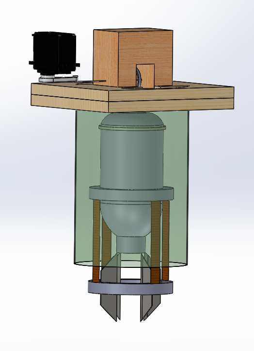
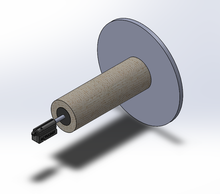
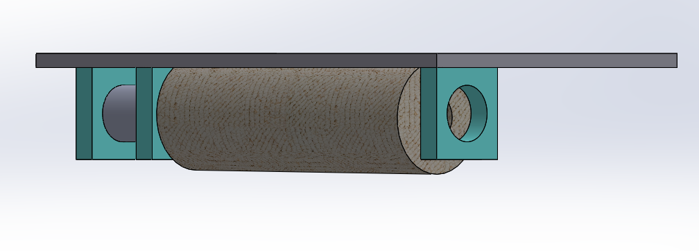
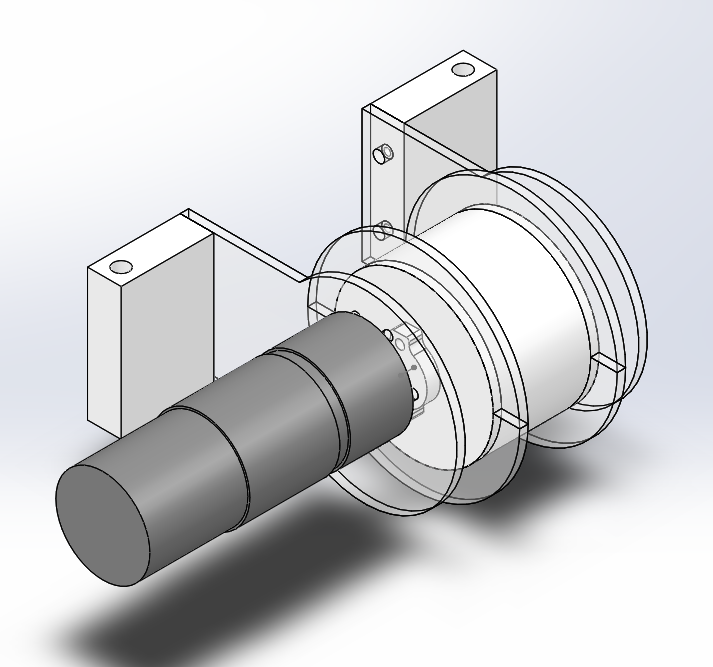
My initial design uses a linear actuator to press a rubber stopper into a shaft to decelerate a reel that the ground vehicle would be attached to. Gravity would be responsible for the lowering, and this device would fight against gravity to keep the payload intact.
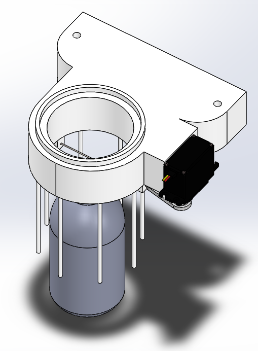
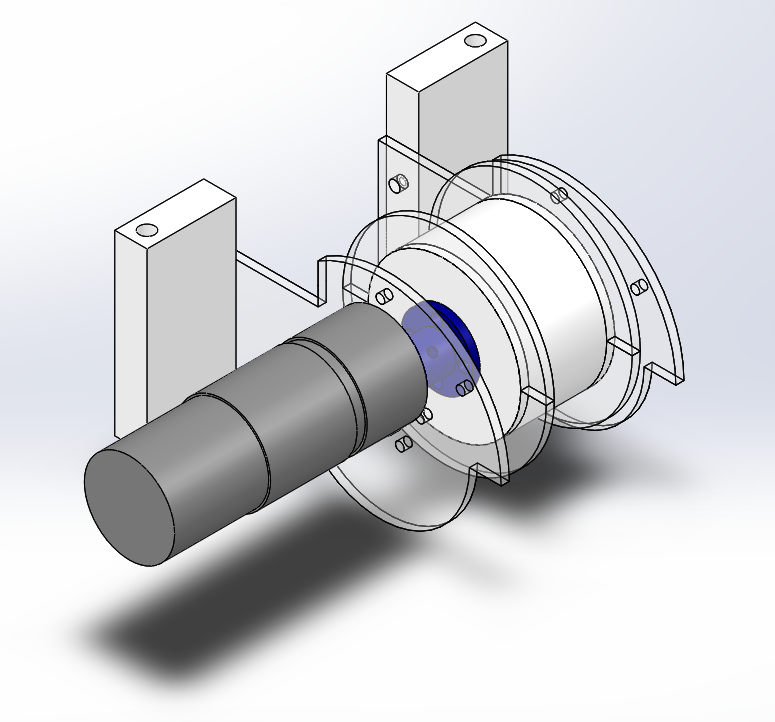
Sometime later, we decided to use a motor as the means of controlling the descent. This model shows a possible mounting configuration.
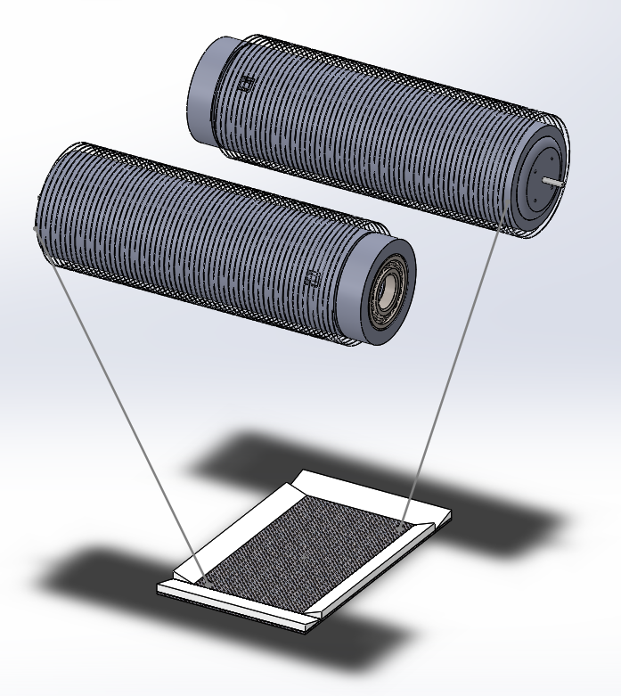
The next iteration of the design involved using a platform to lower the payload. Two spools and motors were used to try to stabilize the platform as it suspended or lowered. Each spool would have a bearing and a motor press-fitted into it. The spools also had a little notch for the string to automatically release. The platform had wedges placed around its perimeter to prevent the vehicle from falling off, but also allow it to drive off.
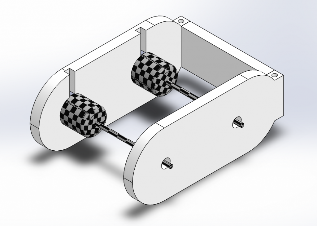
This design evolved to have a similar mounting mechanism as payload drop of the prior year. There are three 3D printed parts that are glued to create the assembly. Two brushless motors (textured to show rotation) and shaft extensions are used in this design. There are spaces for bearings and the motor wires.

To save weight and to take advantage of more optimal manufacturing methods, laser-cut acrylic was used as a substitute for many 3D-printed parts. Brushed motors were used instead of brushless for more torque. This iteration also features flanges that prevent the string (fishing line) from tangling.
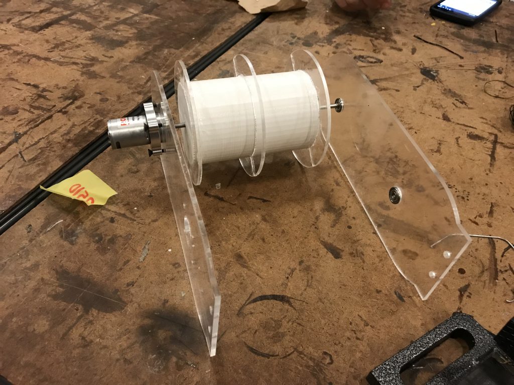
This iteration was fortunate enough to get a physical prototype. Not seen here is a 3D-printed connector that fastens to the spool with machine screws and to the shaft with a set screw. Acrylic glue was used to assemble the flanges and to secure the bearings to the holes.
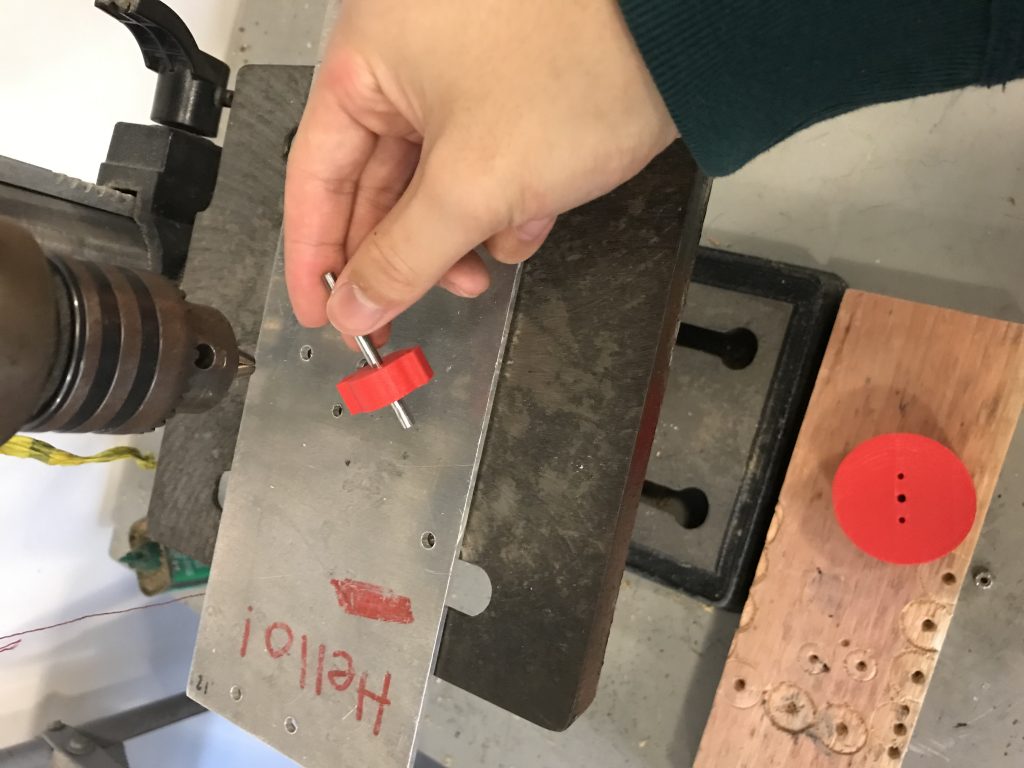
A shaft being pressed fit into a connector using a drill press.
The design was further refined to incorporate an upgraded motor and to have a reduced profile/mass.
The 3D-printed couplers were underperforming, so a metal piece was purchased and the mounting holes on the spool were updated accordingly. The holding pieces were also updated to support a fiberglass covering
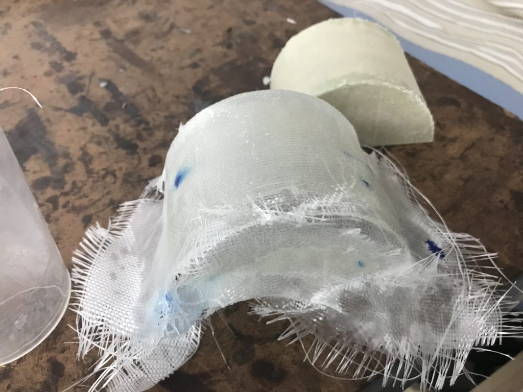
This was my first time working with fiberglass. A male mold was 3D-printed and was used to create a flexible but hard covering
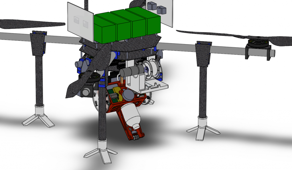
The final assembly of the drone. I collaborated with a teammate to create a part that was capable of supporting the motor.
I was very happy to see that the deployment system ended up working. It was honestly one of the most difficult things I worked on.
2019-2020 Year
This year, I am one of the airframe leads. From what it looks like, I will be working on a 10-week long onboarding program for new members and guiding the design and manufacturing of a fixed-wing UAS.

The program, named UASPIRE, was a crash course on designing a quadcopter. This year, we had 8 members participate. They were exposed to SolidWorks and basic quadcopter assembly.
Being in a leadership position has certainly been interesting. One of the best pieces of advice that I got from a previous lead is to “take a step back and take a big picture approach to things.” I found myself taking this to heart and did more task distribution than actual work for UAS, even though I made sure to go around and offer help. I felt like a manager. This year, the airframe team consists of about 20 members and is led by me and the other airframe lead: Eric Wong. I am grateful for the hardworking and talented team at my disposal, as well as the entire supportive leadership staff.
The plane underwent several major design changes over its first couple of months of digital conception. Some of the reasons for design overhauls are:
- To make manufacturing easier
- The wingspan was hilariously large
- To improve fuselage strength
A challenge that I did not foresee coming was the difficulty that comes with making large purchases. Early in the year, we had the opportunity to order balsa wood together with another organization (Design, Build, Fly), and that has been one of the most stressful moments I have experienced as a club member. It’s frightening knowing that I am a major player in a time-sensitive and financially important decision. Nonetheless, it was a growing experience.
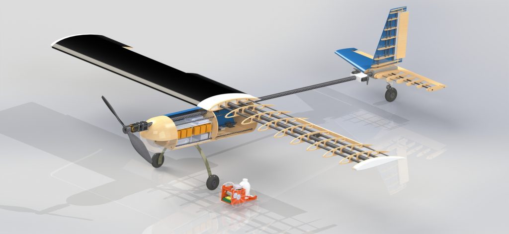
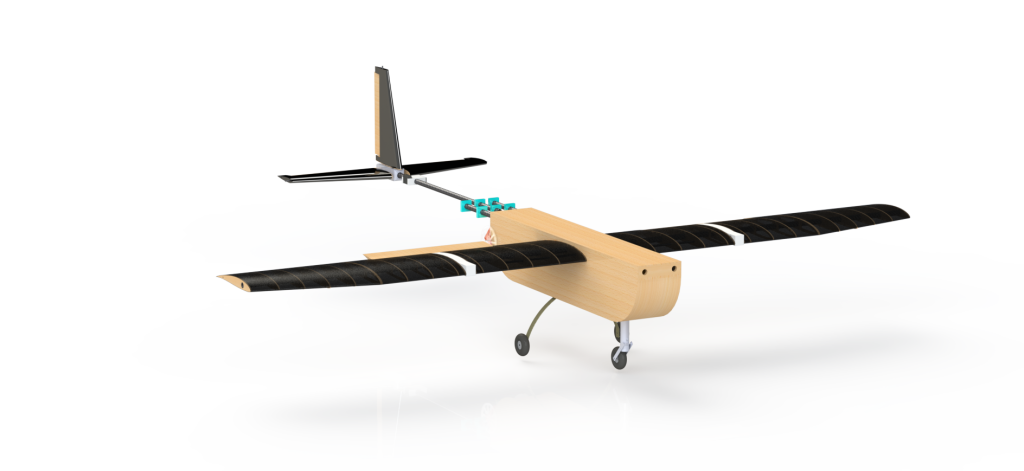
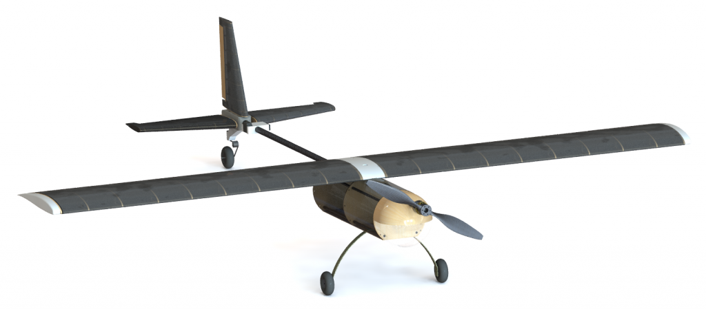
When winter quarter rolled around, we finalized the design of the aircraft and got ready to manufacture. One of my additional commitments during this time was to help make some renders for the team’s crowdfunding campaign.
We managed to raise a whopping $10,000, and you can view the campaign page here. I have to give huge props to people like our club president, David Thorne; our External Vice President, Ryan Alexander; our keystone business member, Lisa Foo; and many others for taking charge of the campaign.
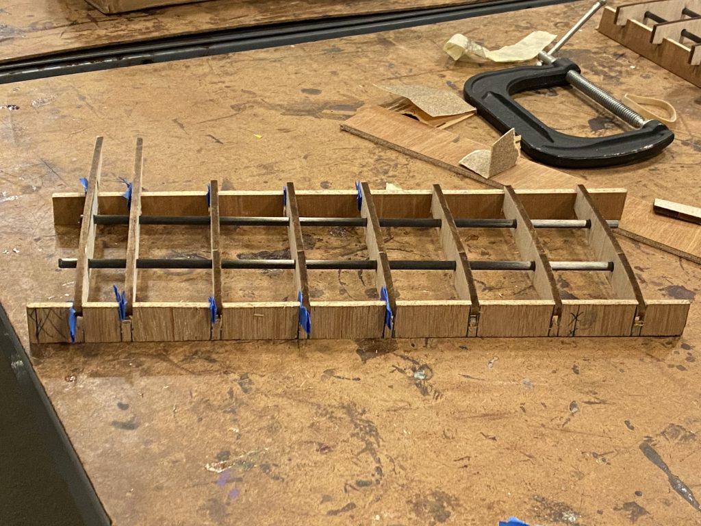
Manufacturing went well, especially for a team with little to no prior experience. We started with the smaller pieces like the tail since a screw-up would be less costly.

After finishing a wing, we realized that it won’t fit inside the golf case that we have been using for several years
Most of the plane is constructed using balsa wood and carbon fiber tubing. The balsa wood was laser-cut and adhered to the support structures with either Gorilla Glue or Zap-A-Gap. We ordered a giant bottle of Gorilla Glue and named it “Harambe.” The sizing of the glue was actually accidental, largely due to my inability to visualize 36 fluid oz.
Ultracote was applied onto our control surfaces (flaperons and rudder) almost as a test piece. After these parts, we used wood veneer to get smoother edges.

A fully assembled wing. Some difficulties manifested with getting adequate clearance and with wrinkling the ultracote.

CAD model of a potential cargo bay mechanism. A servo with a disc horn is connected to a hinge with a pushrod. The platform is free to rotate around a support rod due to 3D-printed bearings

The 3D printed bearings surprisingly worked. One other configuration that was considered was dual-cargo doors. This wasn’t completed before the pandemic shut down the school.

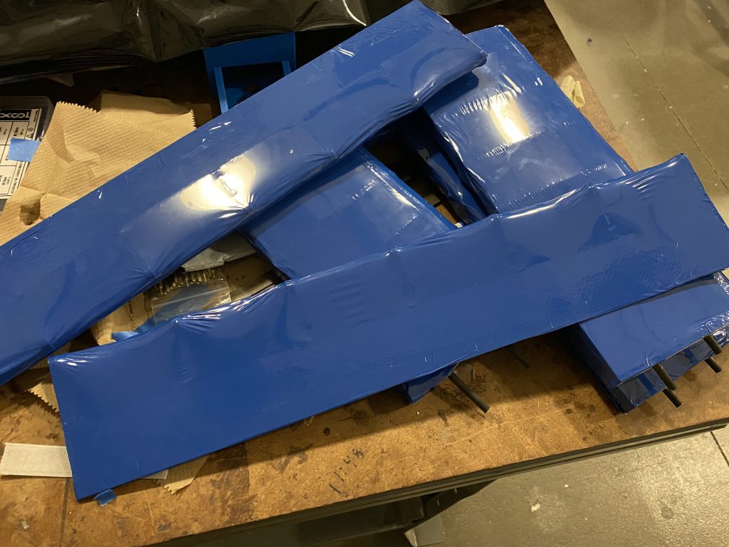
To improve our aerodynamic performance, the team set out to manufacture composite nose and tail fairings out of fiberglass and epoxy resin. We created our male molds using 3D-printing. James Tseng (left) and Allan Zhao (right) are pictured here applying a releasing agent to the mold for the tail fairing.
I think that it is very important to discuss how thankful I am for the subteam and for supporting leadership members. They were absolute all-stars and were instrumental in the (near) construction of the aircraft. Especially for a pretty new leader, my teammates made my life so much easier through their cooperation and willingness to show up, put in the hard hours, and learn.
Another interesting moment with UAS was doing some RC flight training with a flight simulator.
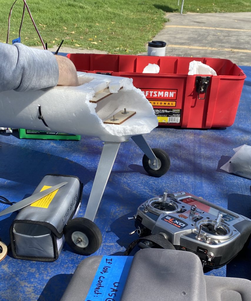
During one of our flight tests, our test plane, Flappy, had its’ rear end explode after a touch-and-go landing.
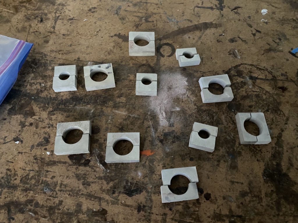
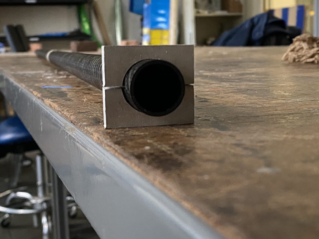
One of the more grueling accomplishments this year was using the waterjet (housed with UCLA’s Rocket Project/Professor Spearrin’s Lab). It required interpersonal skills, some luck, preparation, and a whole lot of time. We were using the waterjet to manufacture tube clamps with a custom diameter since our carbon fiber tubes’ outer diameters were non-standard. Thus, commercial-off-the-shelf components would not work.
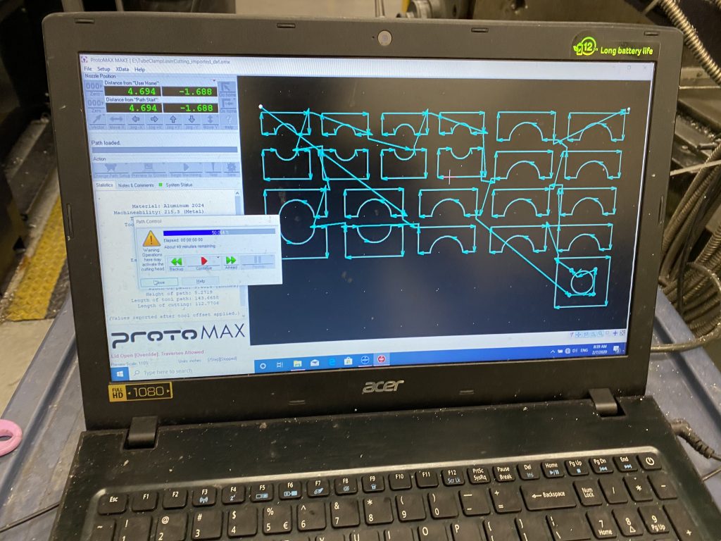
The software used was ProtoMAX layout to set up the path, and ProtoMAX Make to actually control the waterjet. I was given a very brief crash course right before setting up our slab of 6061 aluminum.
At this time, the waterjet (ProtMAX by OMAX) faced a myriad of issues. The drain that was adjacent to the machine got clogged, so I had to get a vacuum cleaner to suck up all the water once the level was too high, and then I had to carry it to dump it in the gutter. Also, every once in awhile the tubing and nozzle would get jammed. This required disassembling the system and relieving the jam with an air gun.
In the end, I spent about 6 hours working on the waterjet, from around 8 am – 2 pm. This was the only time I skipped a class all year. Luckily my some of my teammates arrived in the afternoon and gave me some much-needed support. We would visit the waterjet a few more times after some drilling mishaps.
Using the waterjet for the tube clamps felt like a big personal success for me due to the effort required to get everything accomplished. Everything from waking up extra early, buying the head operator a morning donut and coffee, hauling gallons upon gallons of sludgy water, fixing multiple jams, and mindlessly drilling holes was draining in one form or another.

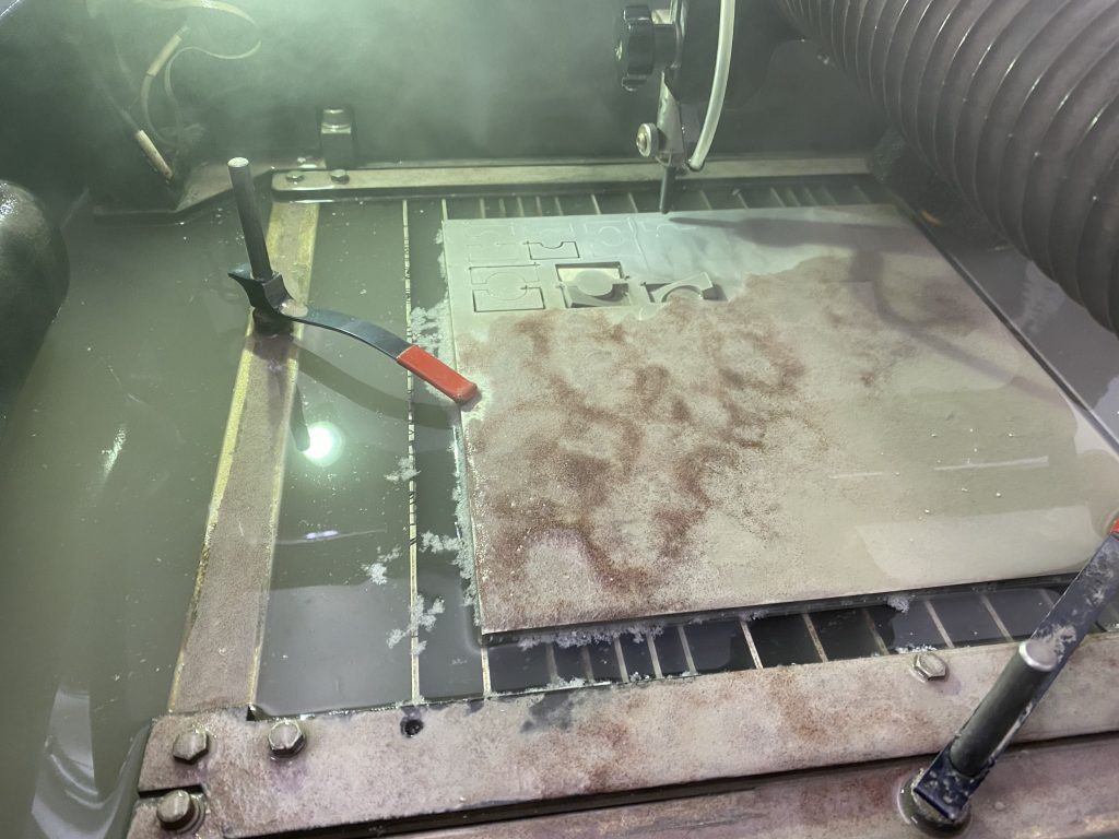
This was the final picture I took at the lab before the Covid-19 pandemic caused the school to shut down indefinitely.
2020-2021 Year
During my senior year, I retained my position as the airframe co-lead. This year, I will be operating remotely for at least the entirety of the Fall quarter. The club is also pivoting from participating in the AUVSI SUAS competition to exploring the NASA Undergraduate Student Research Challenge and the First Responder UAS Endurance Challenge.