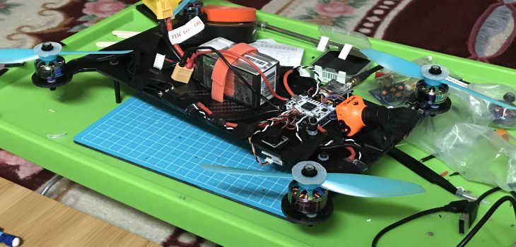
I wasn’t planning on building a quadcopter this summer, but I had leftover flamethrower components from my summer BattleBot purchases and thought that it would be nice to attach to a drone. Later I figured out that this was against FAA regulations and can result in a $25,000 fine. However, my device is simply a glorified blow torch and maybe won’t qualify as a dangerous weapon, similar to Elon Musk’s Not a Flamethrower. $25,000 is a pretty good deterrent though, touché FAA.
Initial Research
I honestly knew very little about quadcopters when I started this project compared to now. My objective was to build a vehicle that would be capable of carrying the small flame device I was planning to build at a moderate cost. I initially planned to build a tricopter because I thought that I could save money on a motor and ESC. However, a tricopter would be more complex to build from scratch and did not look like a good introductory build.
Off the bat, I decided that my quadcopter should use a 4S battery and have an FPV camera so it can still be used for fun. To reduce costs, I decided to source most of the parts (except for transmitter and frame parts) from GetFPV. I custom ordered my frame from Protech Composites.
One of the first challenges that I faced was powering the flame device. I initially thought of powering the ESC that powers the ignitor through the drone’s flight controller and power distribution board. In fact, that was one of the reasons why my first thought was to build a tricopter; I was planning to replace a motor with a blowtorch.
I solved this problem by thinking outside of the box. The solution was to make the blow torch and the quadcopter two independent systems. This way, not only is the electronics simplified, but the drone can have a blowtorch-less configuration. I went to Amazon and purchased the cheapest non-sketchy 2-channel transmitter/receiver combination and a small 2S battery.
Components
- Lux V2 flight controller
- Lumenier 35A ESCs
- Matek FCHUB-6S PDB
- Lumenier 5.8 GHz FPV Transmitter
- RunCam Swift 2
- Lumenier DXII antenna
- FatShark Recon
- Spektrum DSMX receiver
- Matek Buzzer
- Lumenier 2450KV motors
- Tattu 4S 1550mAh 100C Battery
I chose the Lux V2 as my flight controller because it looked cool it has DSMX support, or more specifically, it has the option to power either a 3V or 5V transmitter, and the DSMX receiver can only take 3V. It also wasn’t too pricey and has been used numerously on YouTube.
When choosing the PDB, the only things that I cared about was that it was able to run on 4S and had space for an XT60 connector. In hindsight, I should’ve checked for compatibility with my ESCs.
When choosing my ESCs, I was sort of blind. At the time, I didn’t know what BlHeli was, and I just made sure it was 4S compatible and capable of drawing a moderate amount of amps. In the future, I would definitely like to use some newer ESCs, one equipped with BlHeli_32 instead of BlHeli_S so I could make custom startup jingles.
When I chose my motors, my limiting factors were my ESC specs (35A continuous, 45A burst). I estimated that my drone could weigh a generous 3 pounds, so the thrust of each motor combined had to be 1360g just to hover. I was aiming for a 3:1 thrust-to-weight ratio, meaning that each motor e should be capable of providing 1020g of thrust. The motors that I chose should, at best conditions, generate 6000g of thrust altogether. To be honest the motor data of GetFPV could use some work. Anyways, I chose two sets propellers that would’ve provided more than substantial thrust, which meant 6″ props.
The battery that I chose had the lowest price, but the highest capacity (and therefore flight time), so how could I not choose it?
While doing antenna research, I learned that I should have antennas with the same polarization (Left-handed vs Right-handed circular polarized), so I added a set of LHCP antennas to my GetFPV order. One of these would go on the FPV transmitter and the other would go on my goggles.
I threw in a buzzer for absolutely no reason. It was cool and very cheap compared to everything else already in my cart. I envisioned being able to trigger it on a switch, but that is still a work in progress.
CAD Model
After getting a rough idea of my components, I started to CAD. I modeled the electronic components first based off of their website descriptions.
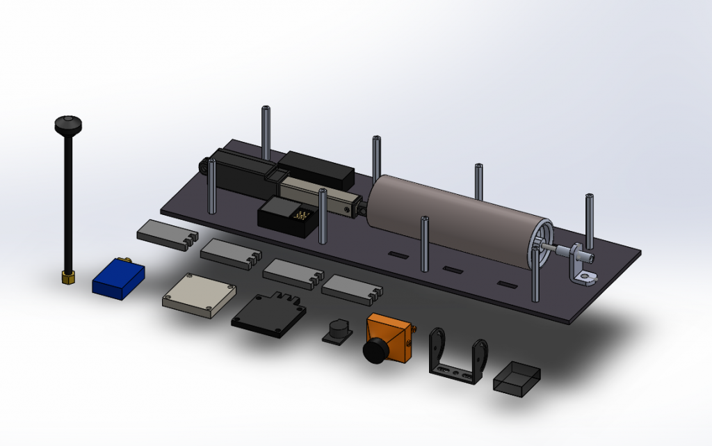
Only one of the propellers I purchased was modeled. I mostly free-handed it based on the online image (only dimensioned the diameter). I then made an offset extrude and tried to capture the pitch with a flex feature. One important detail is the motor mounting; it is a perpendicular set of M3 holes, one on a 16mm and another on a 19mm circle.


Design tables were utilized (generated with excel equations) for the standoffs connecting the blowtorch platform to the main frame. This allowed me to adjust both the diameter of the hexagon and the height at ease.

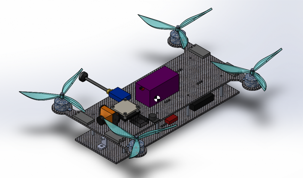
I used sketch blocks to create the motor mounts on the drone. I mirrored the arms, but not the mounts because I needed to make sure that the wires pointed in the correct direction. The sketch blocks I made had direction indicator arrows. I used slots instead of normal clearance holes to give me tolerance in case my model was inaccurate.

I made the motors extend as little out as possible to save on manufacturing costs. In the main frame, we can see holes for velcro to secure the battery, spare velcro slots, mounting holes for PDB/FC stack, holes for FPV camera, and holes for standoffs.

The final model had the drone of having the dimensions of 12″ x 7.3″ (excluding propeller tips), and weighing ~2.1 lbs (excluding fasteners and wires)
Construction
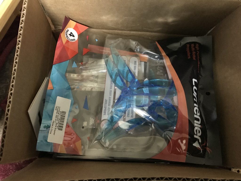
The amount of joy I felt was proportional to the amount of pain my dad’s credit card did.
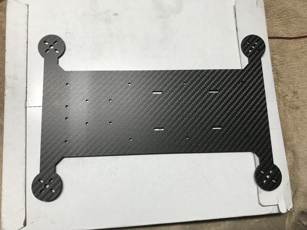
It’s always cool seeing the physical representation of a design, especially if it’s your design.
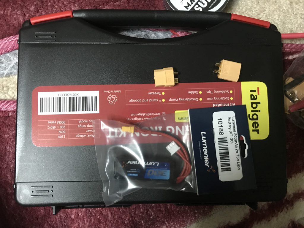
The first order of business is to get my soldering up to speed. I will attempt to add an XT60 connector to my small 2S battery
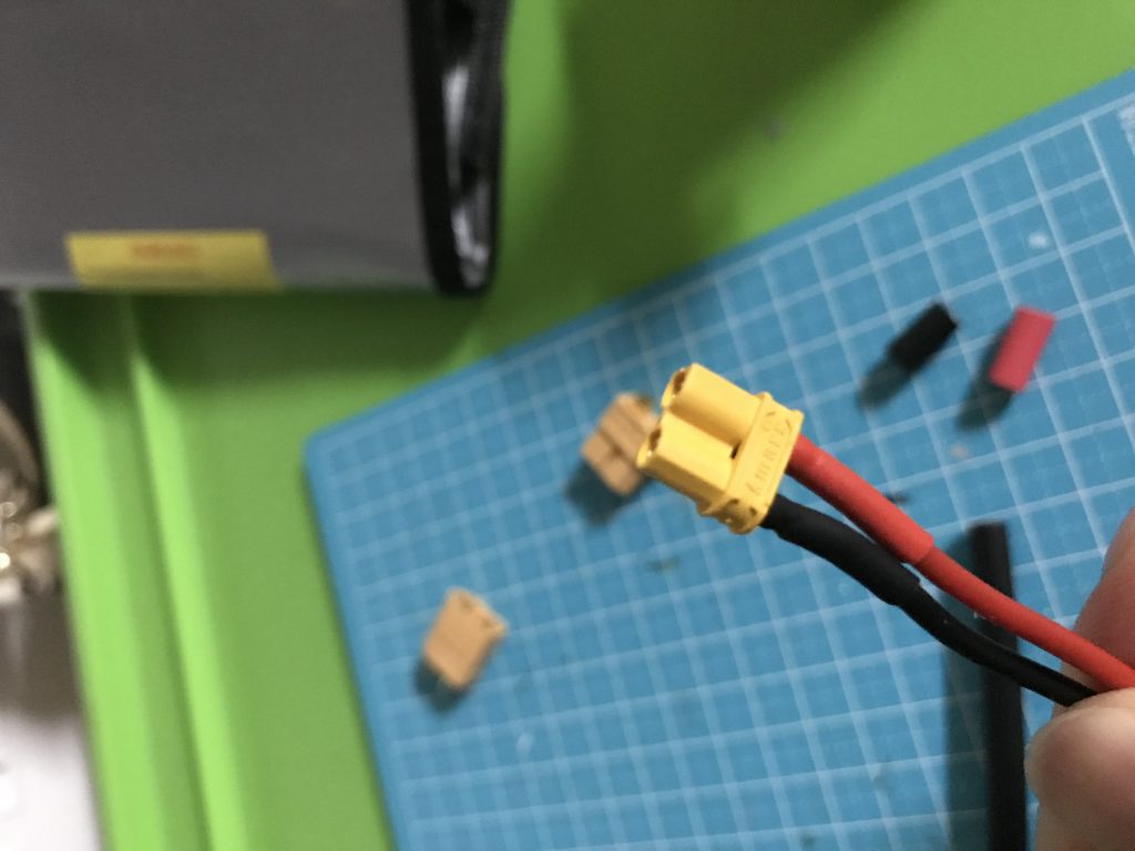
It originally came with an XT30. I must be careful when removing the wires to not cause a short.
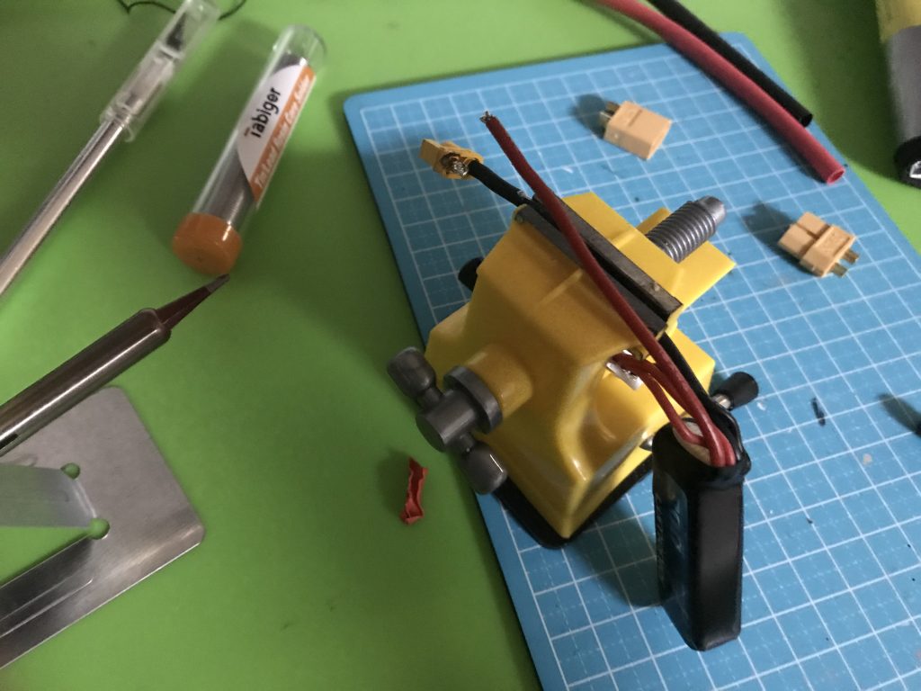
I don’t have any helping hands or puddy, but this mini-vise from Daiso should do.
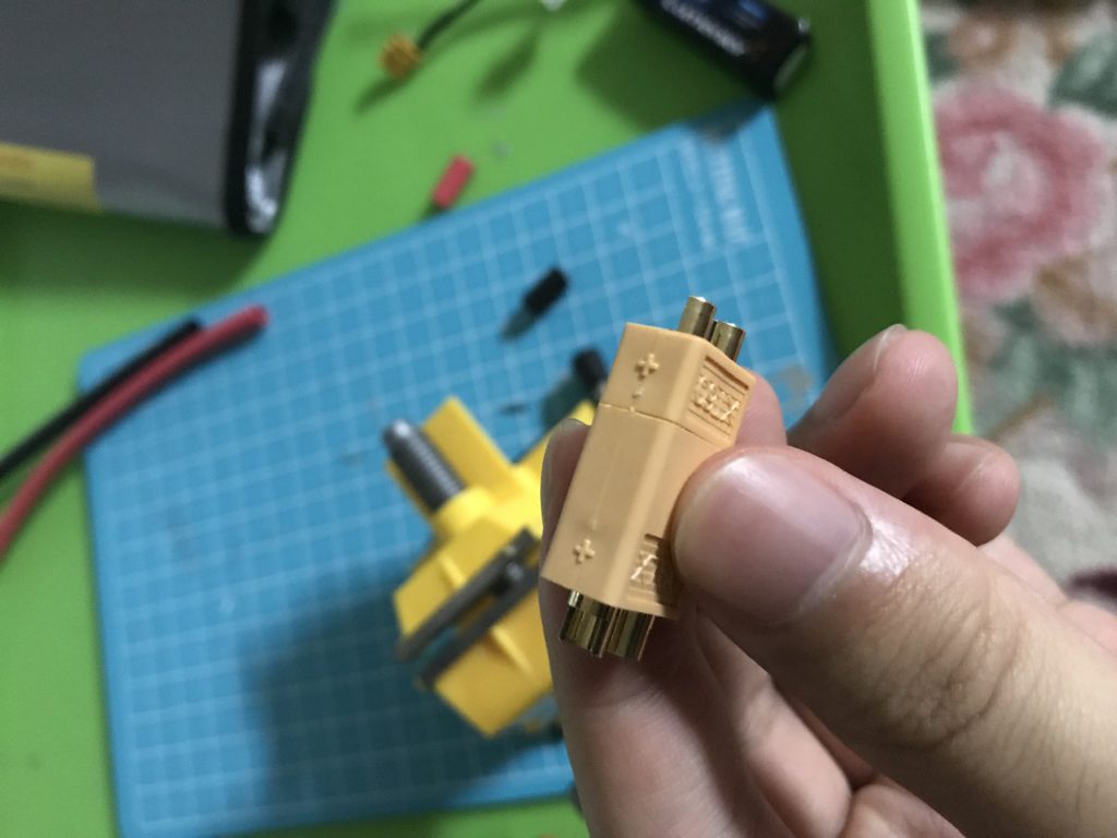
Even though I will be attaching a male XT60 to the battery, inserting it in the female end will prevent it from deforming due to the heat
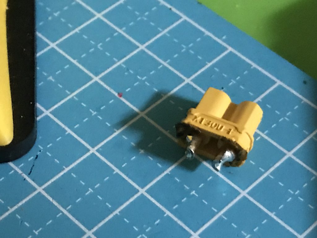
Successfully removed the XT30 without setting my house on fire
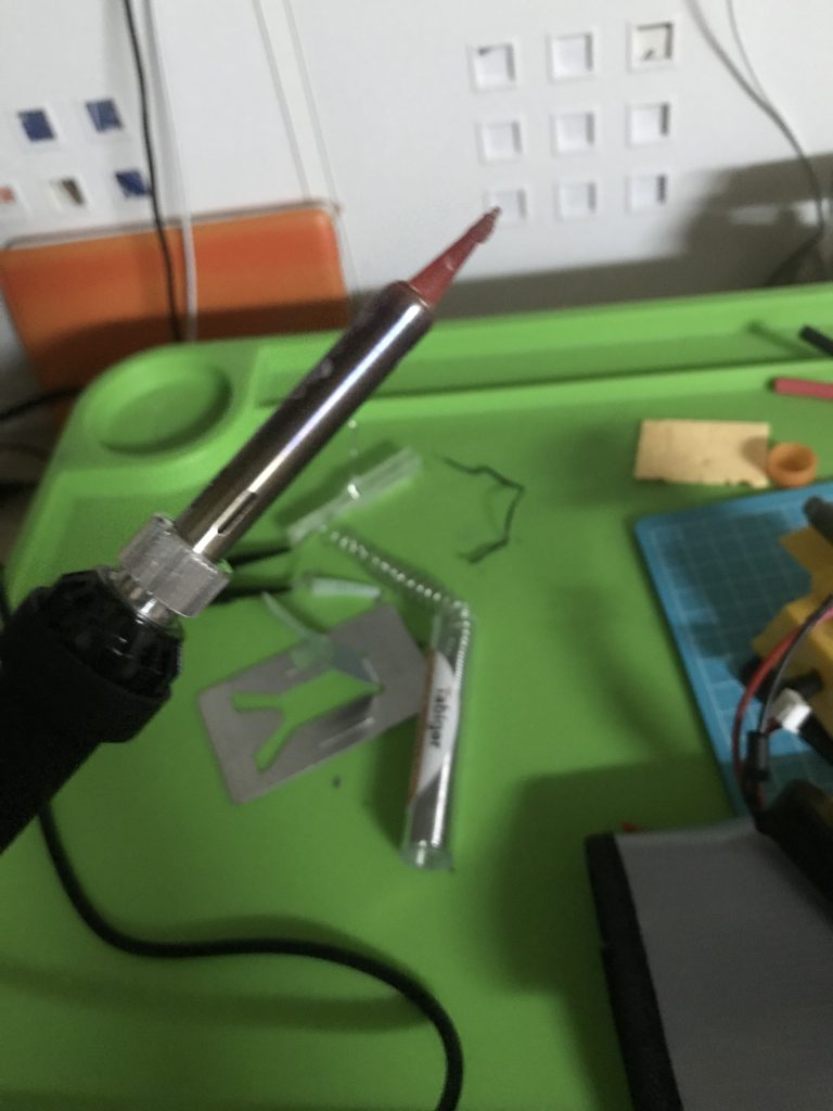
This reminds me of the red-hot knife fad that was on YouTube briefly. I quickly realized that making the soldering iron as hot as possible is not the best idea. Also in the future, I would like to invest in a more expensive iron (preferably on that I can turn off)
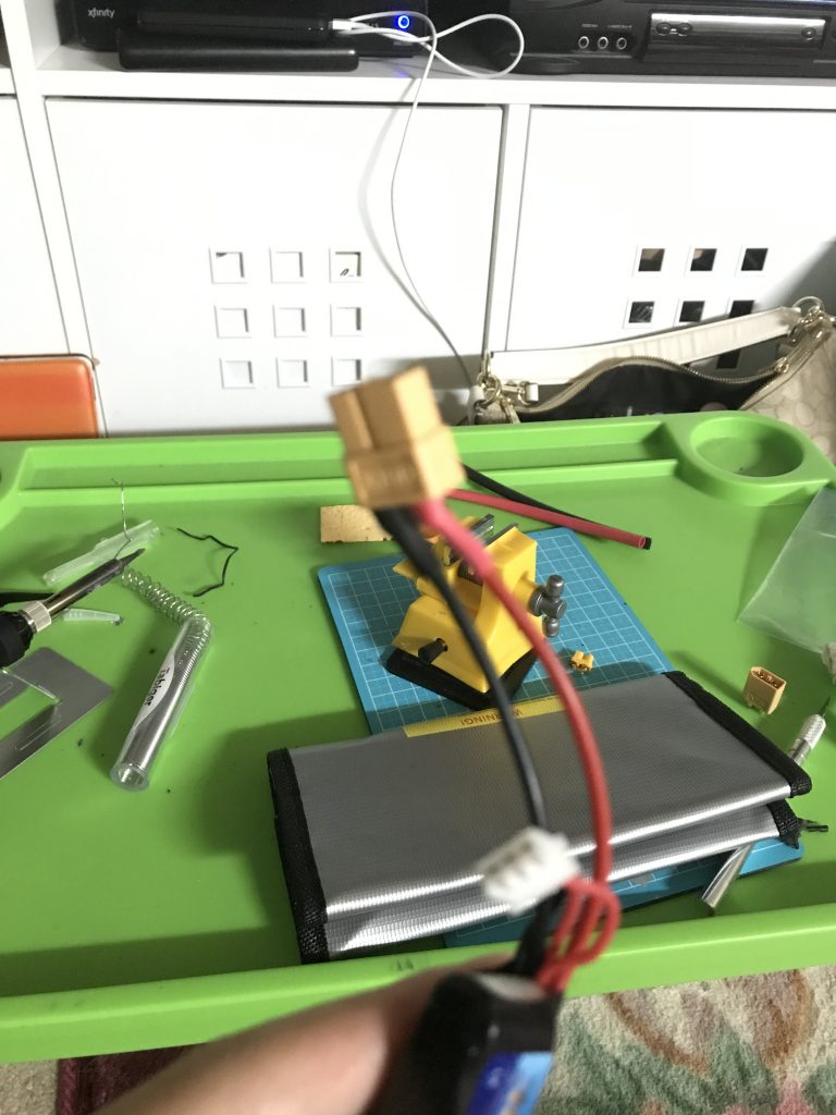
The XT60 has been successfully attached.
A minor setback, I got kicked out of the living room because my dad says that the soldering stinks. On the bright side, I get to bond with the squirrels.
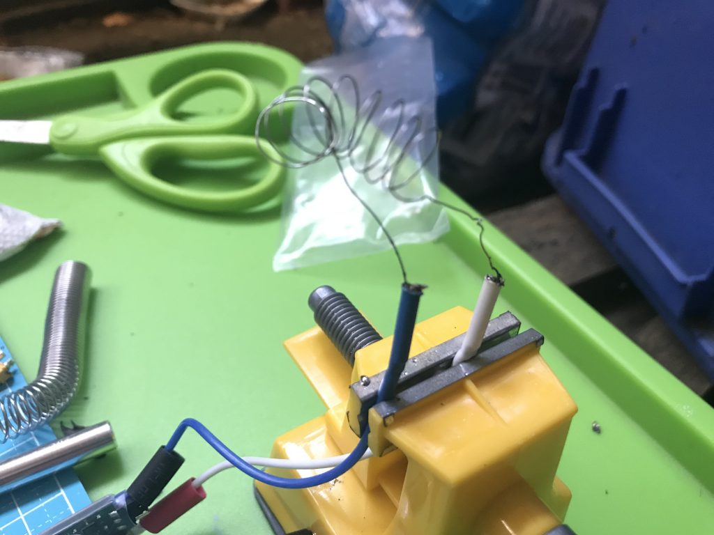
I tried making a coil out of nichrome wire and attaching it to a speed controller. This hasn’t been tested yet, but will be re-done. I also needed to install an XT60 female connector the ESC.
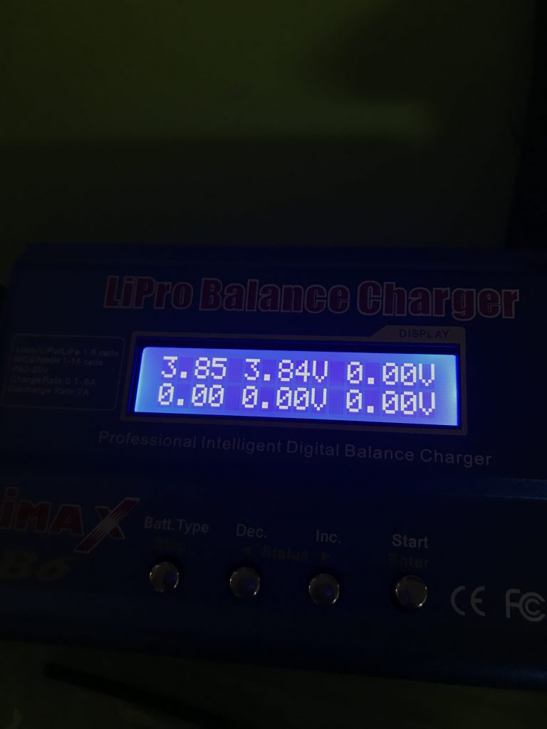
Double good news, my off-brand LiPo charger works and was good enough to charge the 2S battery. Right before this, I watched a YouTube video about how to spot a copycat charger and learned that mine is one of them.
The brushed ESC comes with a built-in 5V BEC, which is enough to power both the servo and the receiver.
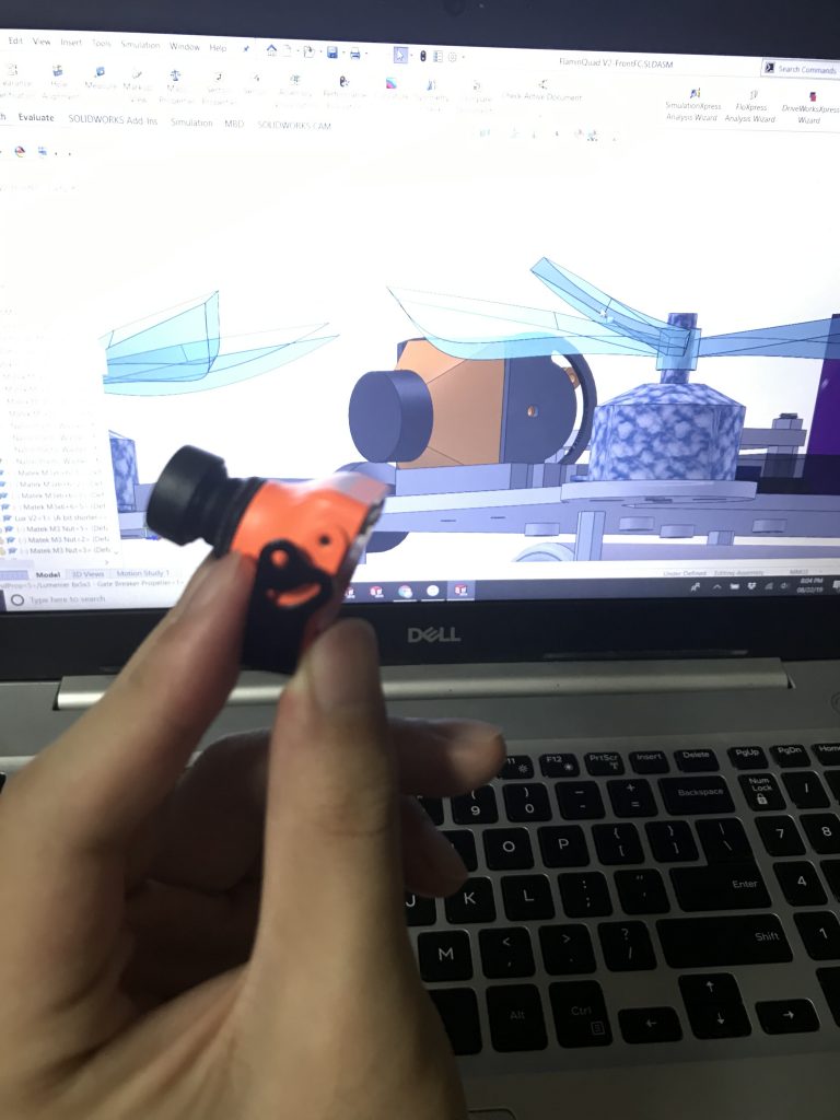
The next step for me was to mount the RunCam. I was a bit disappointed to see that my model was a bit off.
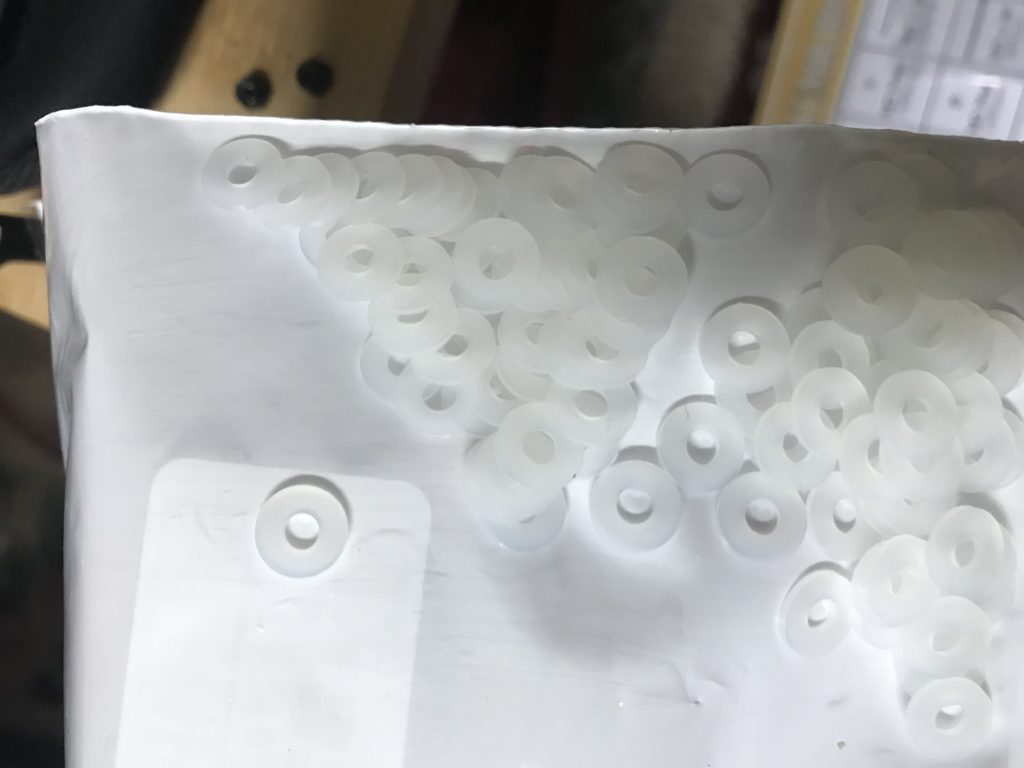
These white nylon M3 washers are my new best friends. So much love for them.
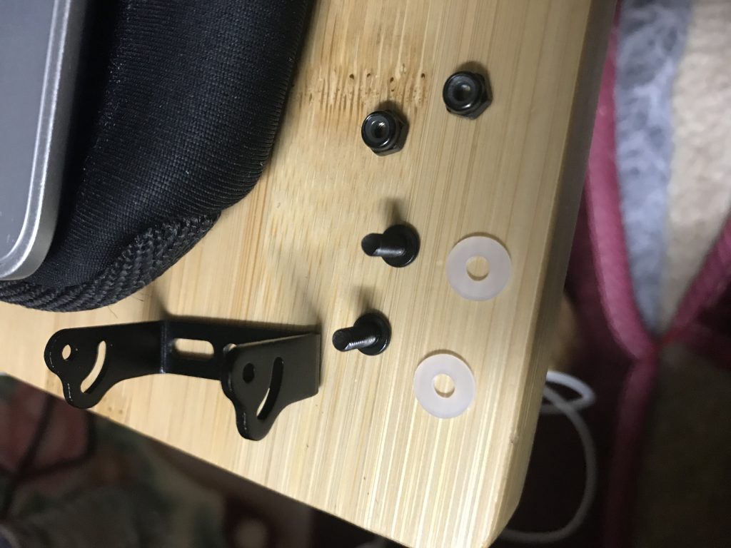
The camera mount is fastened to the frame by two M3 screws, hex nuts, and washers.
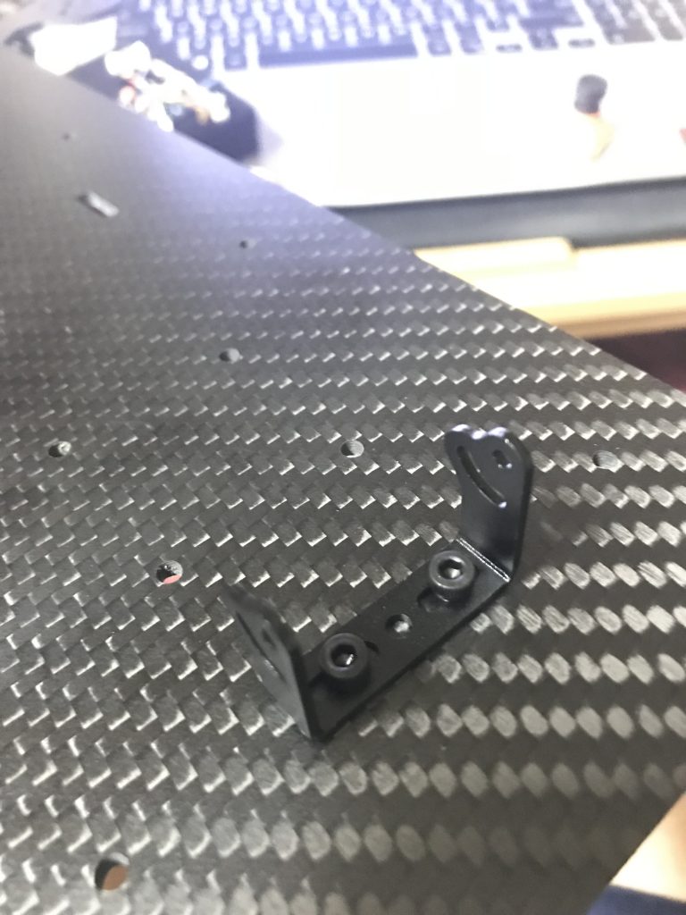
The mount is secure.
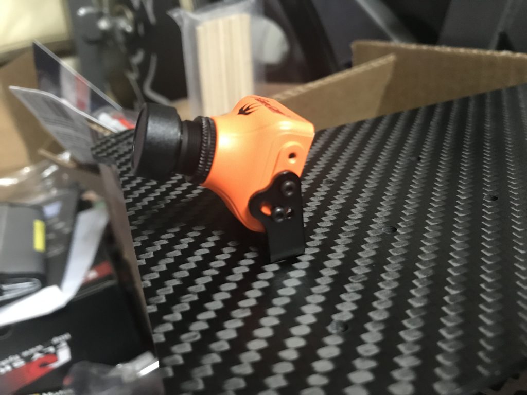
The final position of the camera, it is adjusted at an angle so that it isn’t pointing at the ground when the quadcopter moves forwards.
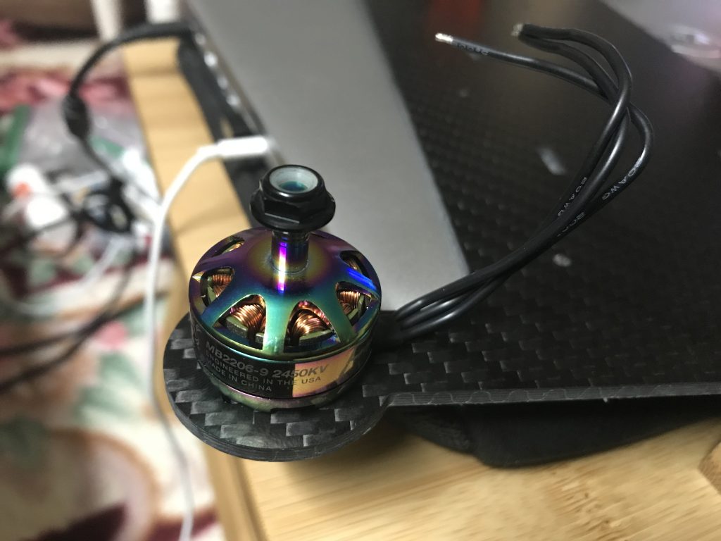
Testing the position of one motor.
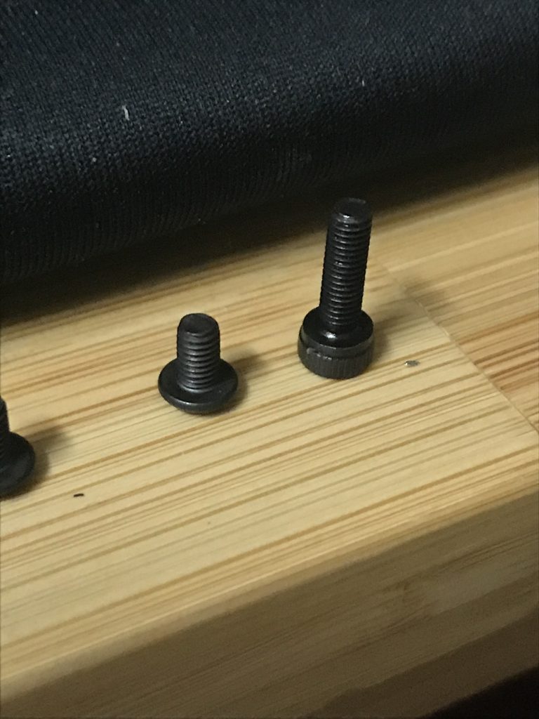
I chose the bigger screw. This was a mistake (see a bit below), and I am lucky that I only fastened one motor initially.
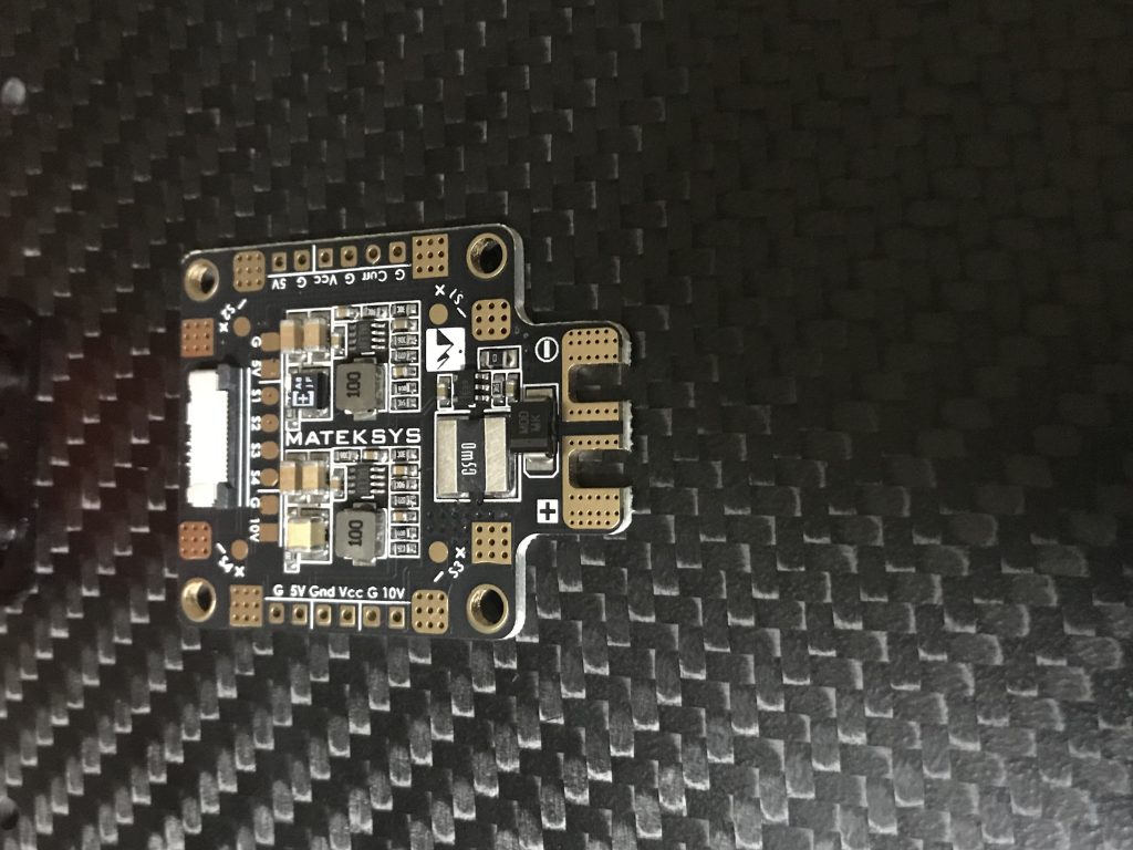
Pretty happy that the PDB holes aligned with that on the frame.
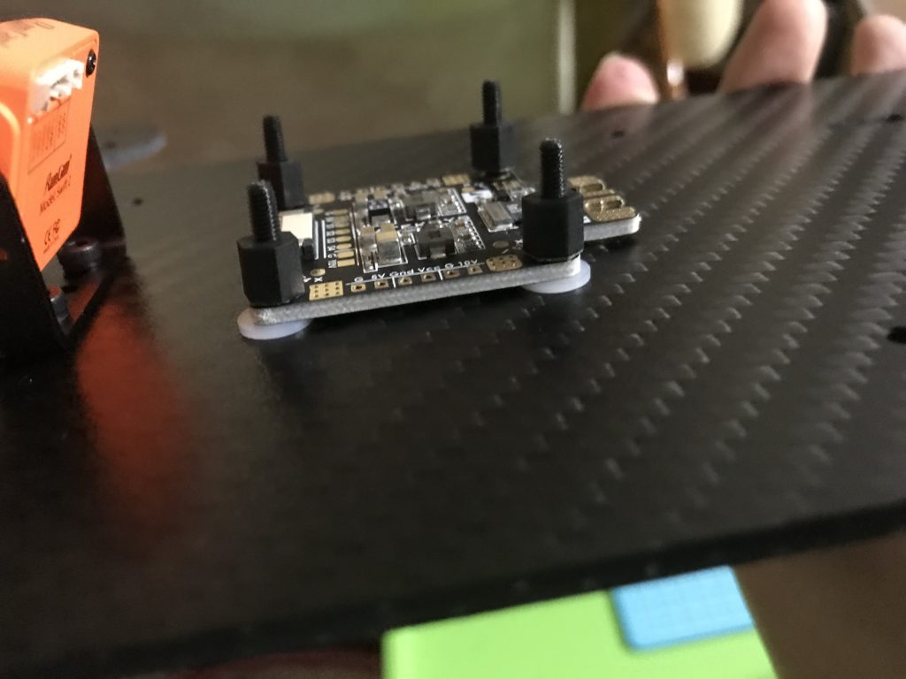
It is very important to add spacers between the PDB and the carbon-fiber frame. Carbon fiber is conductive and can short the PDB
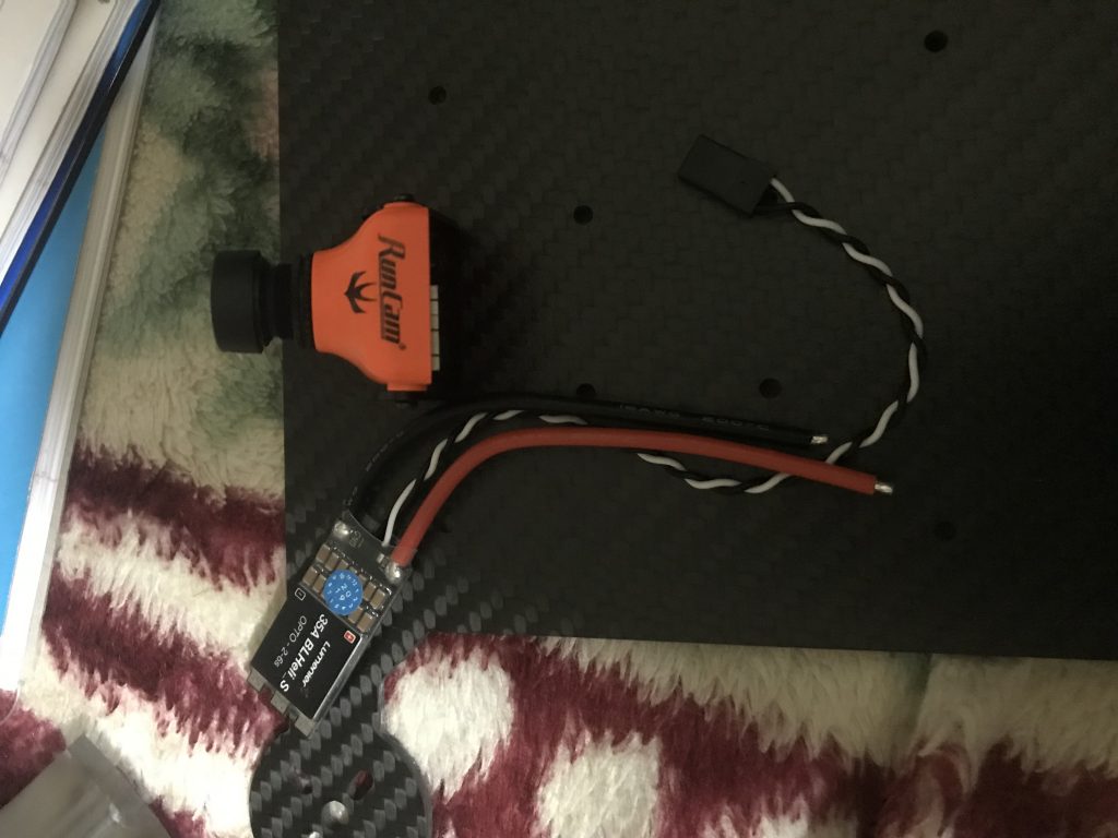
Test fitting the ESC, and realized that my CAD model did not account for the wires and they are not that flexible
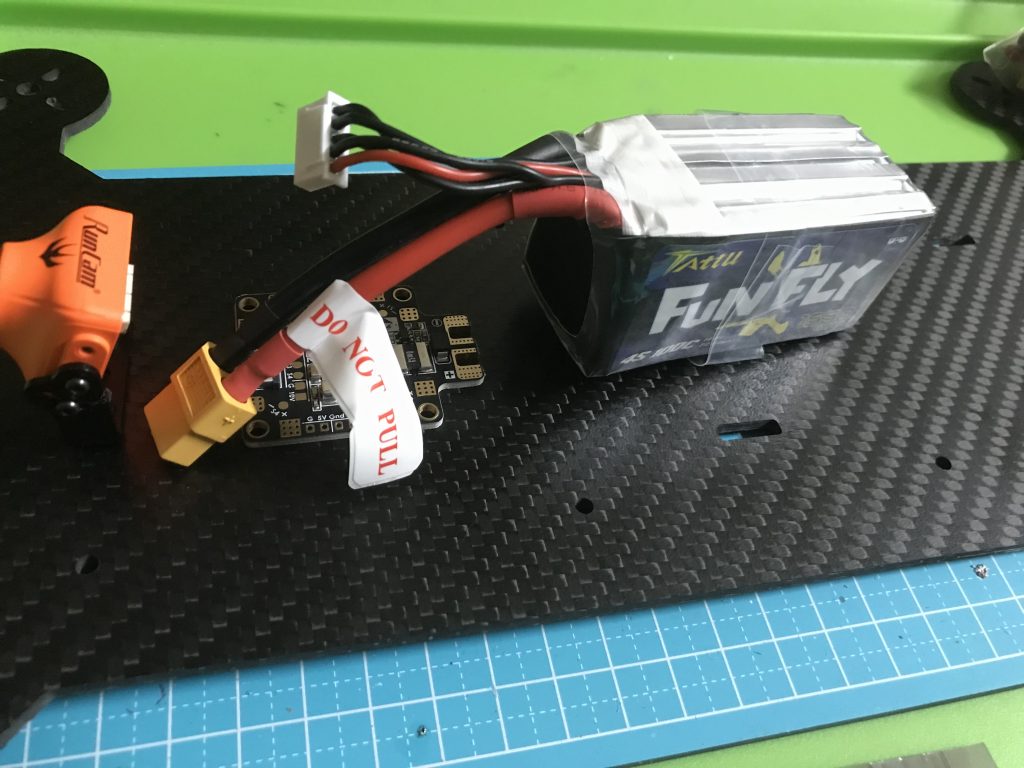
Another instance of my CAD model not accounting for the stiffness of wires. This battery orientation will not work
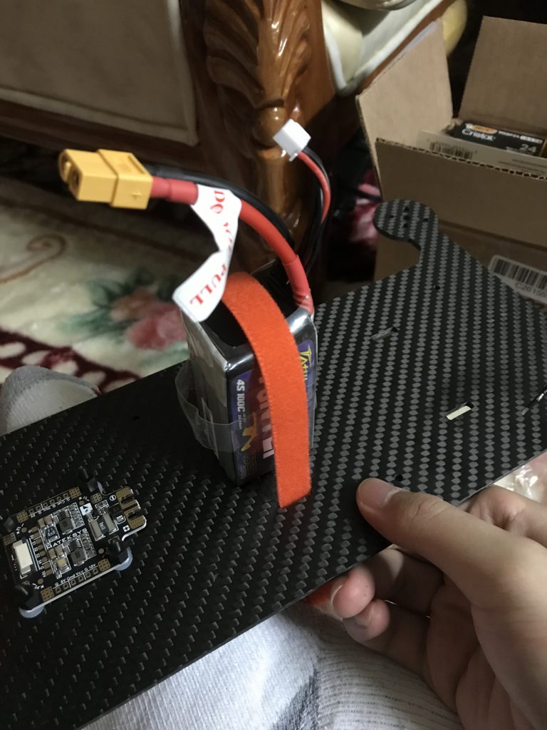
Honestly, I contemplated this orientation for an embarrassingly long time
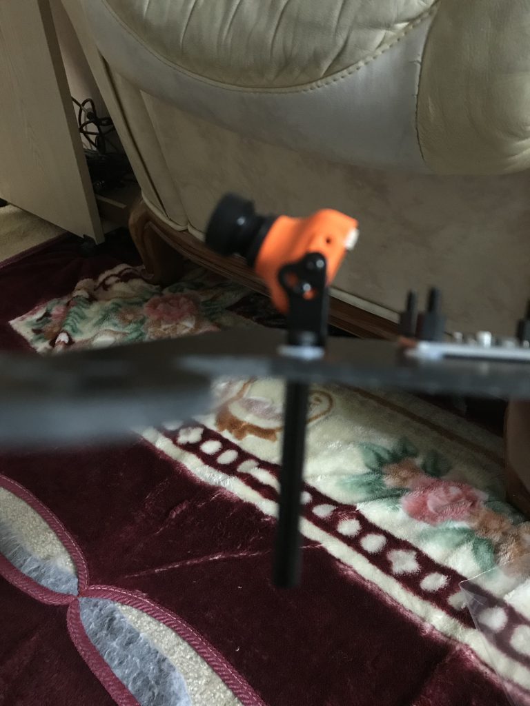
Installing a guinea pig standoff
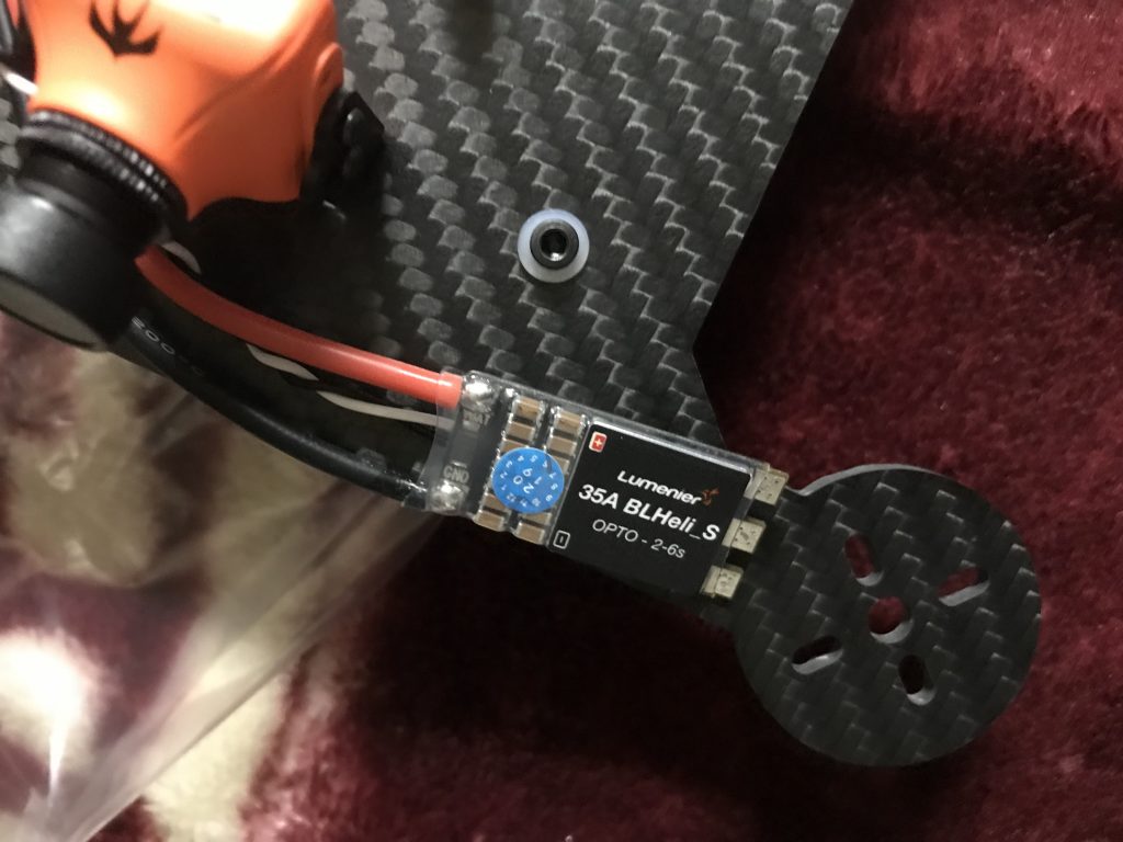
Looking at some ESC placement options
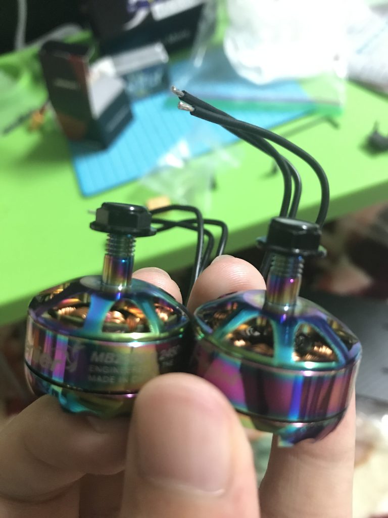
I noticed that one of my motors was not spinning. Remember those long screws I decided to use? They pushed the windings and magnets of the motor and got them stuck to the outside set of magnets. Notice how you can see the magnets on the left motor sticking out
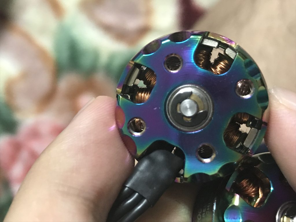
Additionally, the screws dug holes into the wire. I was lucky to have only lost one motor to this lack of foresight.
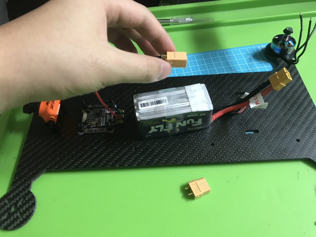
I ordered a new motor in shame and went back to playing with the PDB. Then, I decided to turn the battery around and use a pigtail connector
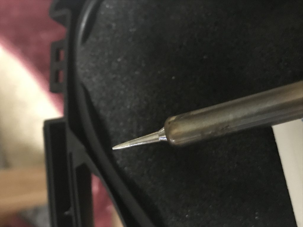
My new buddy is this finer soldering tip. It will hopefully help me solder the tiny pads.
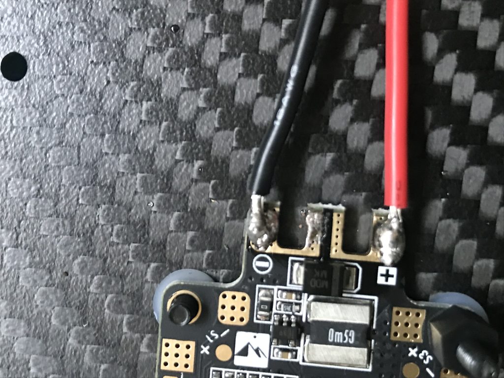
So this connection may not exactly be ideal…
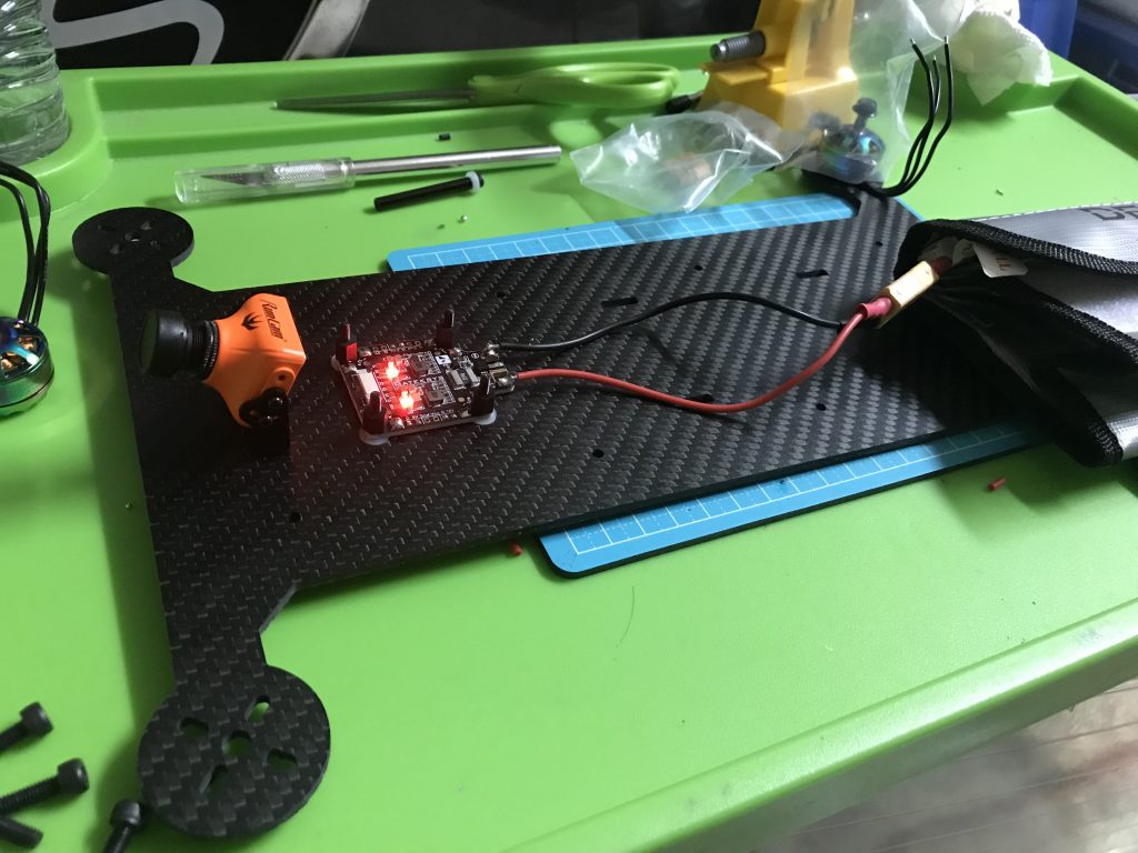
…but it works. I also managed to tin all the pads I needed with only minor damages to one standoff
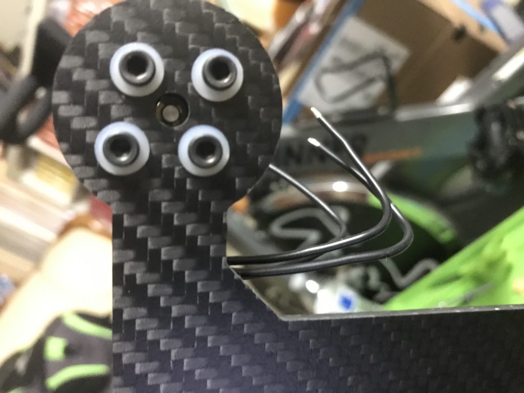
A problem I noticed with my motors is that I made the center hole too small, and the retaining ring keeps getting caught, preventing my motor from spinning.
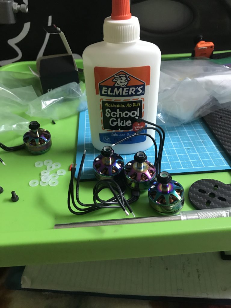
My solution was to use Elmer’s glue. I will glue washers to the motors to elevate it just enough that the retaining ring doesn’t get caught.
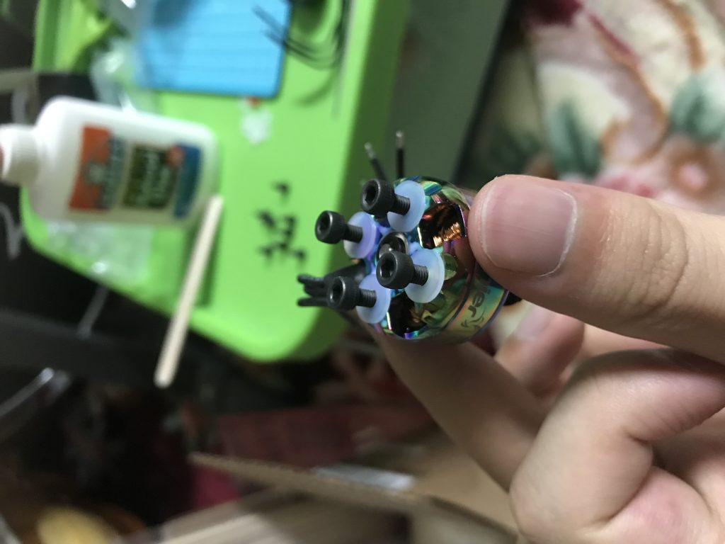
Cautiously using screws as braces/guides for the washers
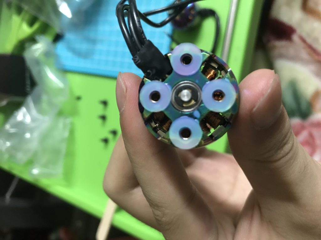
Result not looking too bad.
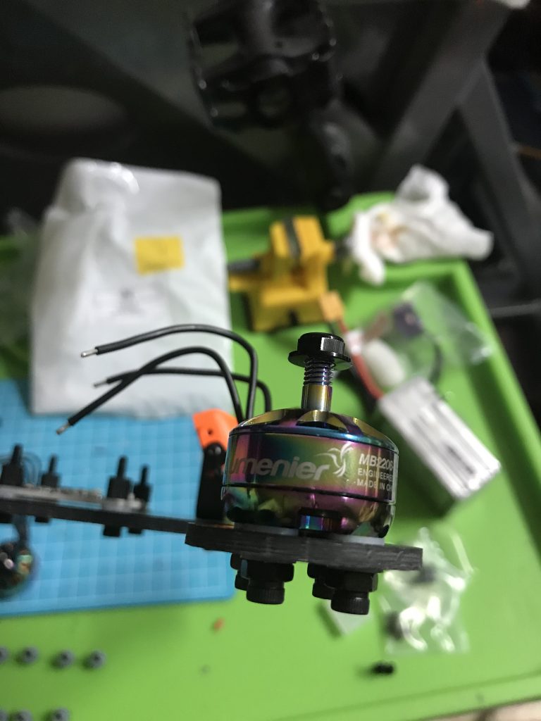
Used M4 (oversized) hex nuts as big washers for longer M3 screws.
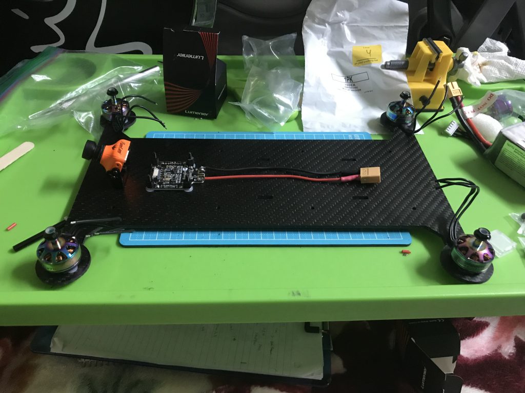
All the motors attached.
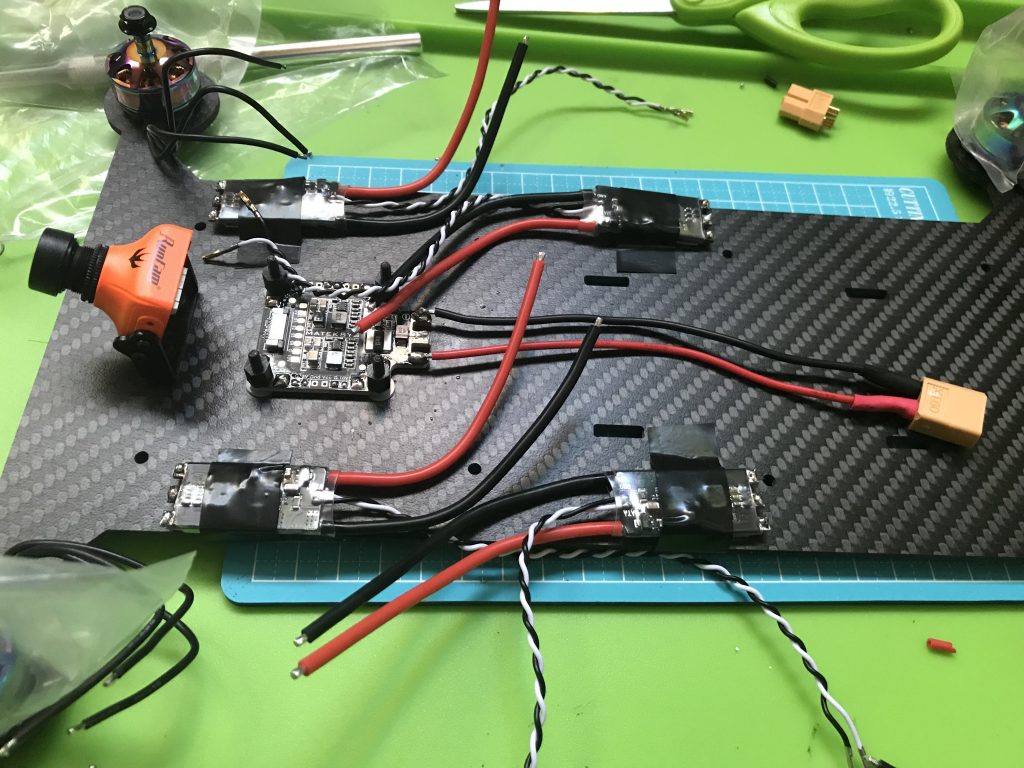
Tinned all the ESCs, removed plugs, and positioned them with electrical tape.
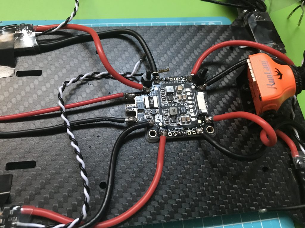
Soldered ESCS to PDB
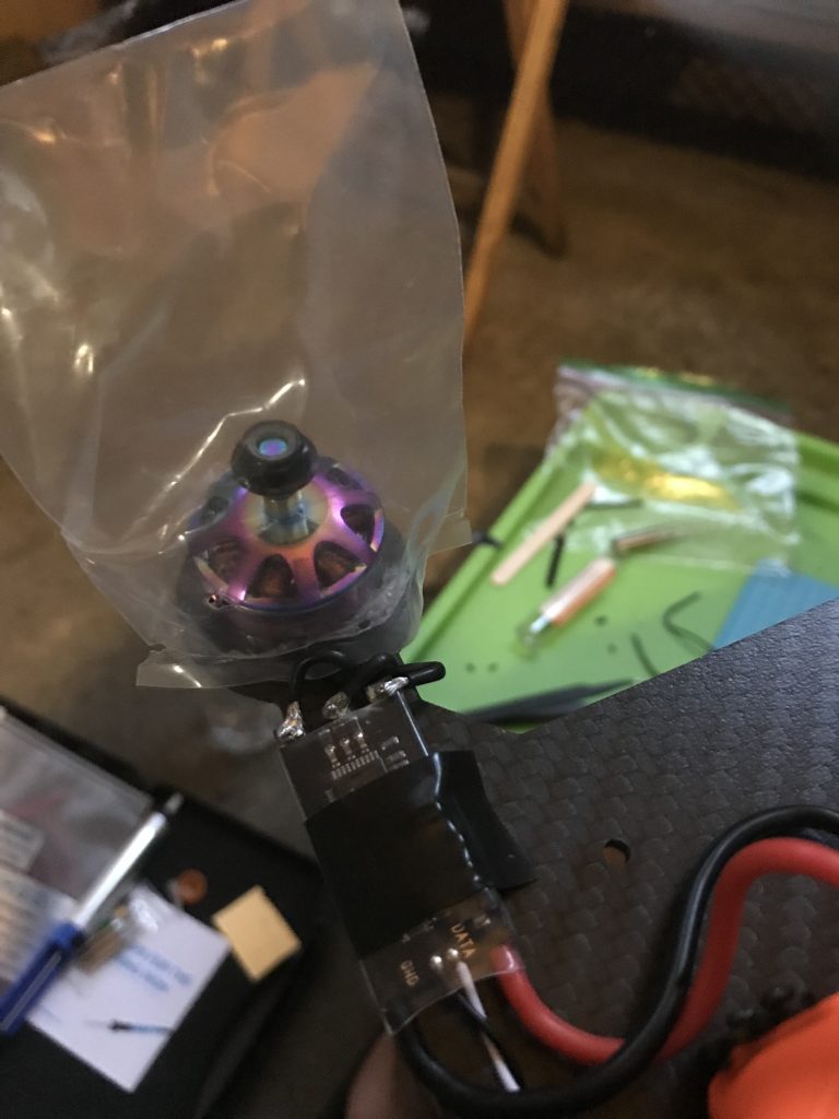
Being paranoid about protecting my motors from the elements. Oh, that and soldering the motors to the ESCs
Let’s take a break from inhaling fumes and check in with the flight controller.
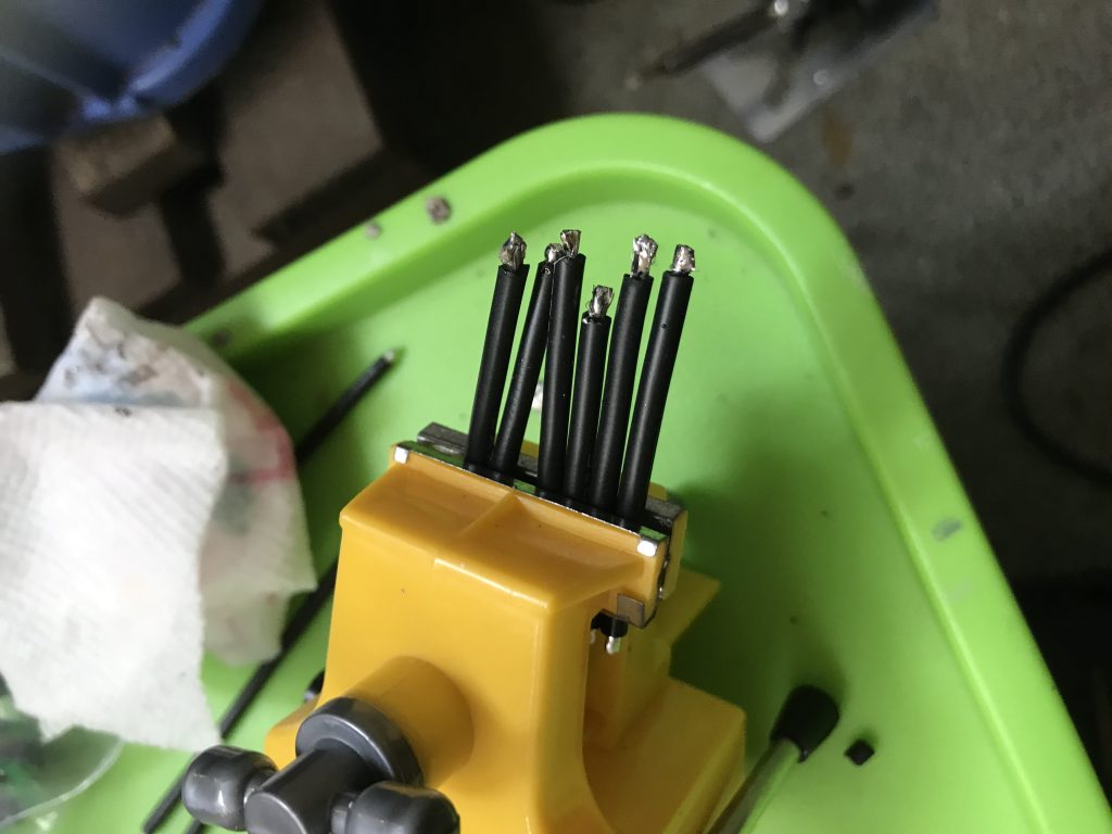
Back to inhaling fumes, right now, we are mass-tinning a bunch of wires.
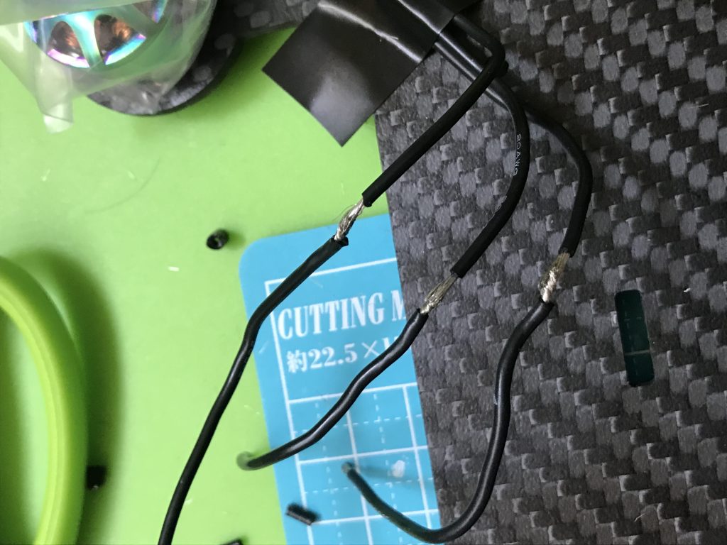
They will make my motor wires longer so they can be placed further away from the ESC. In hindsight, I should’ve only tinned one side, and twisted the other with the motor wire.
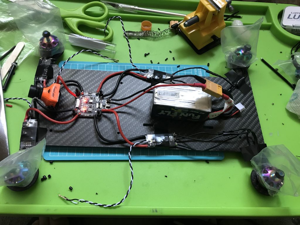
All ESCs wired up to motors. Plus, when I plugged in the battery, nothing exploded
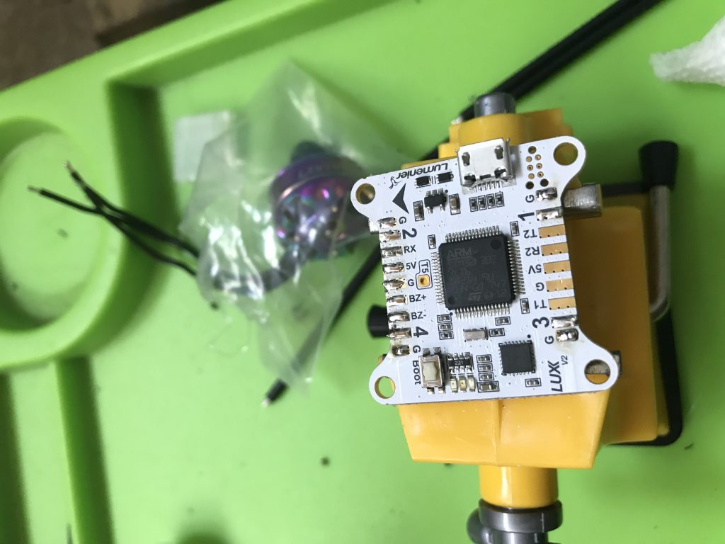
Tinning pads on LUX V2 for ESCs, transmitter, buzzer, and to receive power from PDB.

Squirrel water break
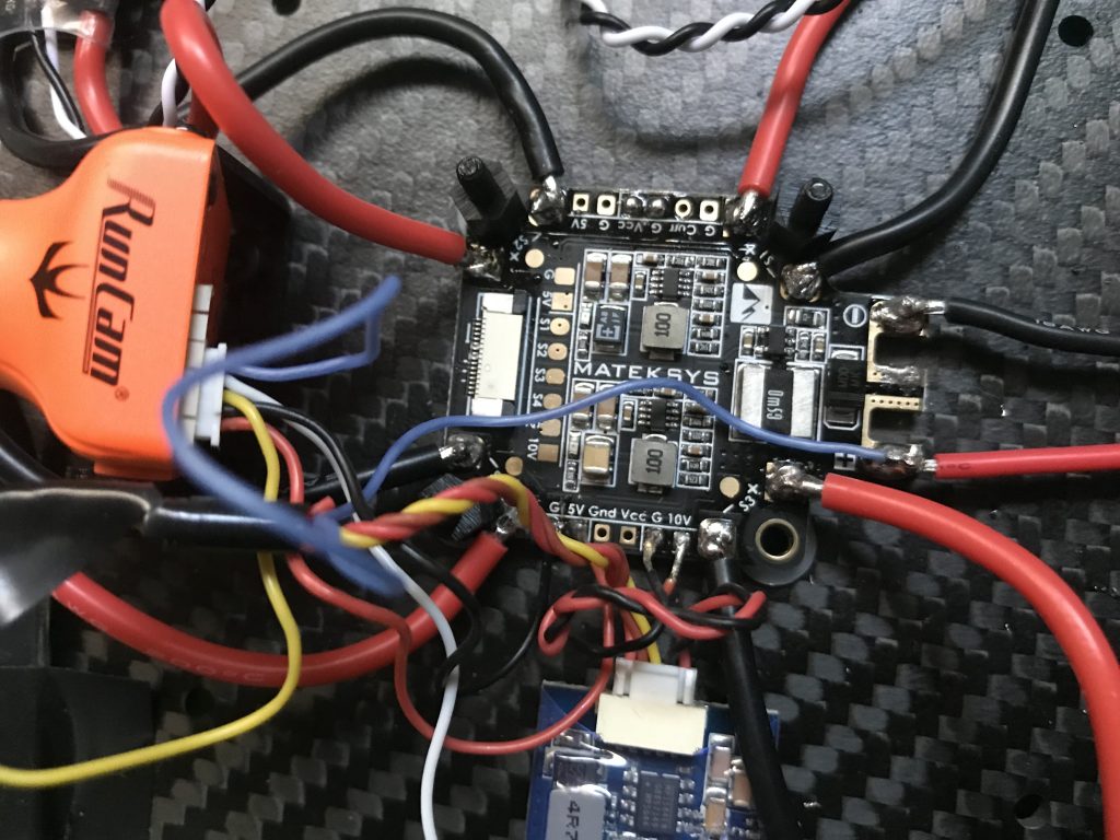
The VTX and camera were painful to work with. I had to connect their yellow wires for signal, solder them to their respective voltage and ground pads, solder the blue wire to the voltage input to monitor it, and leave an umbilical cord hanging out of the VTX.
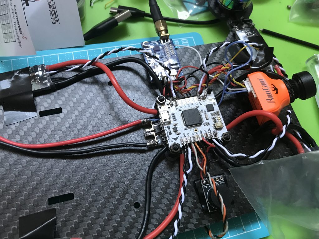
Wiring everything almost gave me a stroke. The soldering quality is definitely not top-notch.
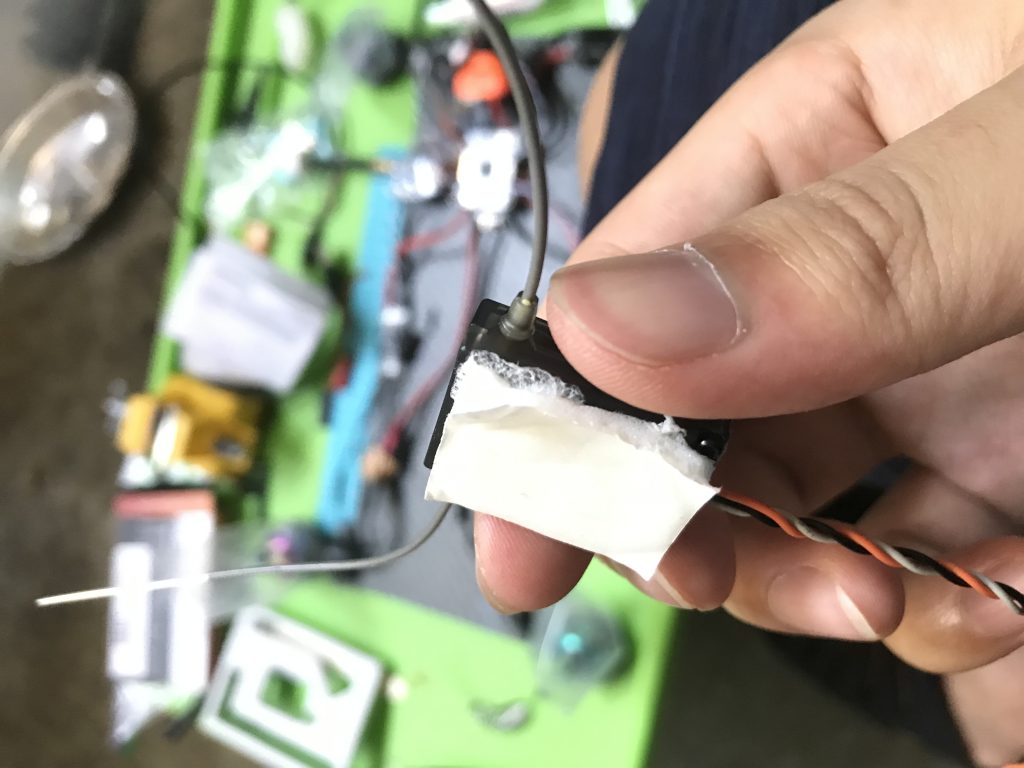
I couldn’t peel off the other side of the double-sticky foam tape and now I have this weird goop stuck to my receiver.
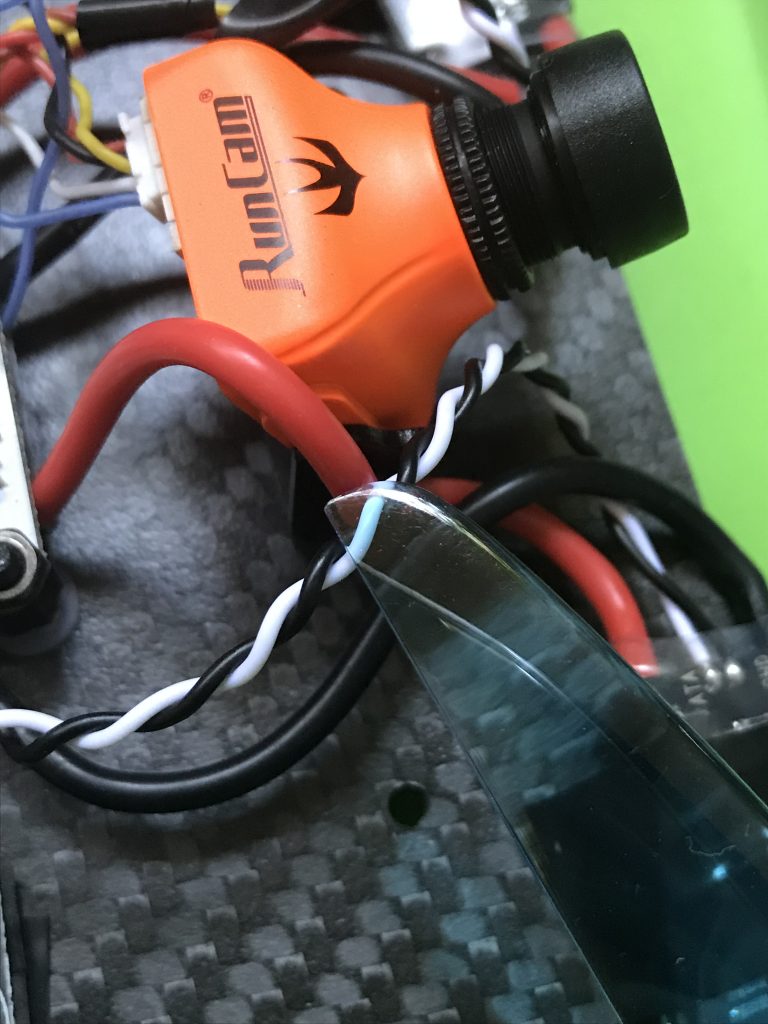
A bit hard to make out, but my quadcopter wants to cut itself.
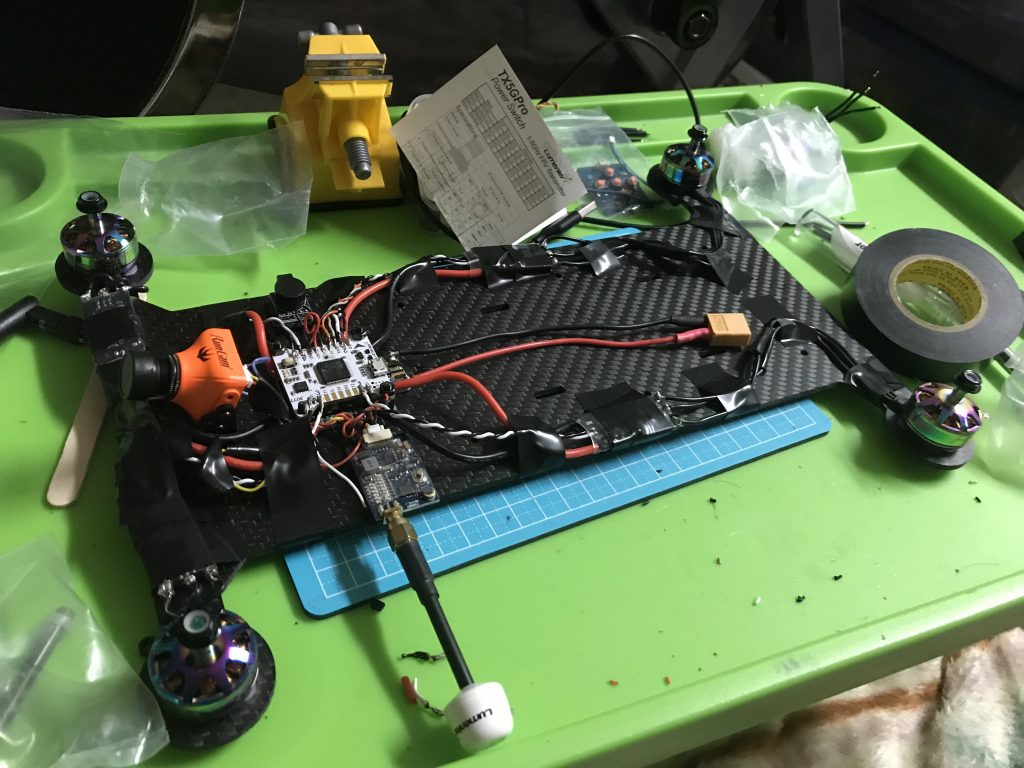
Finished soldering!
Some testing of the gyroscope on BetaFlight, with some Dead Files annoyingly in the background
First time plugging the LiPo into the finished system. This took place next to the door in case anything caught on fire, so I could easily chuck it out. I also notice that it is annoying hard to unplug the battery (maybe I have fake XT60s?)
Testing each motor, the electronics seem to be holding up well!
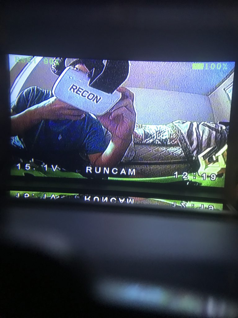
After learning that there is a button to turn on the VTX, I got the FPV system working also. Also, notice the 15.1V indicates that the voltage monitor works.
It was easy to bind the receiver and transmitter, but it took me a while to figure out how to arm it (automatically disarmed when plugged into a computer, had to disable that)
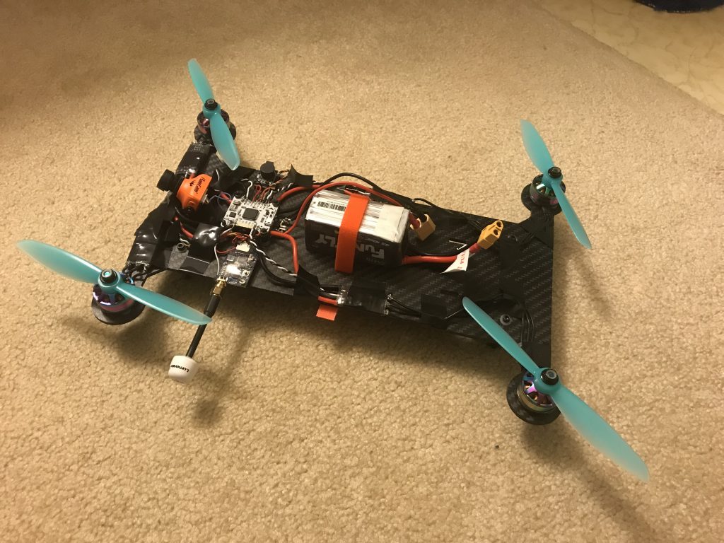
Around this time, I fixed the over-tight XT60 with a pair of pliers. A new and more significant problem arose; the propellers were not tight. They could spin independently from the motor, and I had no M5 washers.
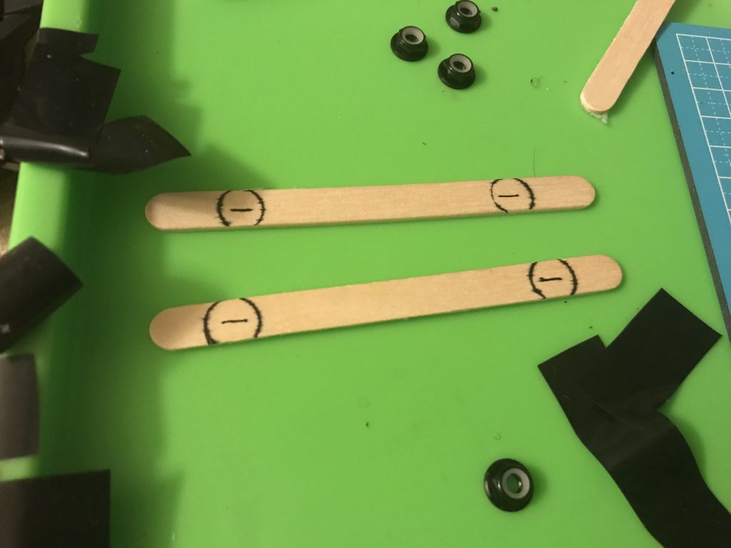
I tried to make my own washers out of popsicle sticks using an X-acto knife and a hex key…that did not go so well (they broke and I gave up on them)
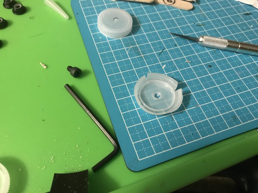
Water-bottle cap washers were the way to go.
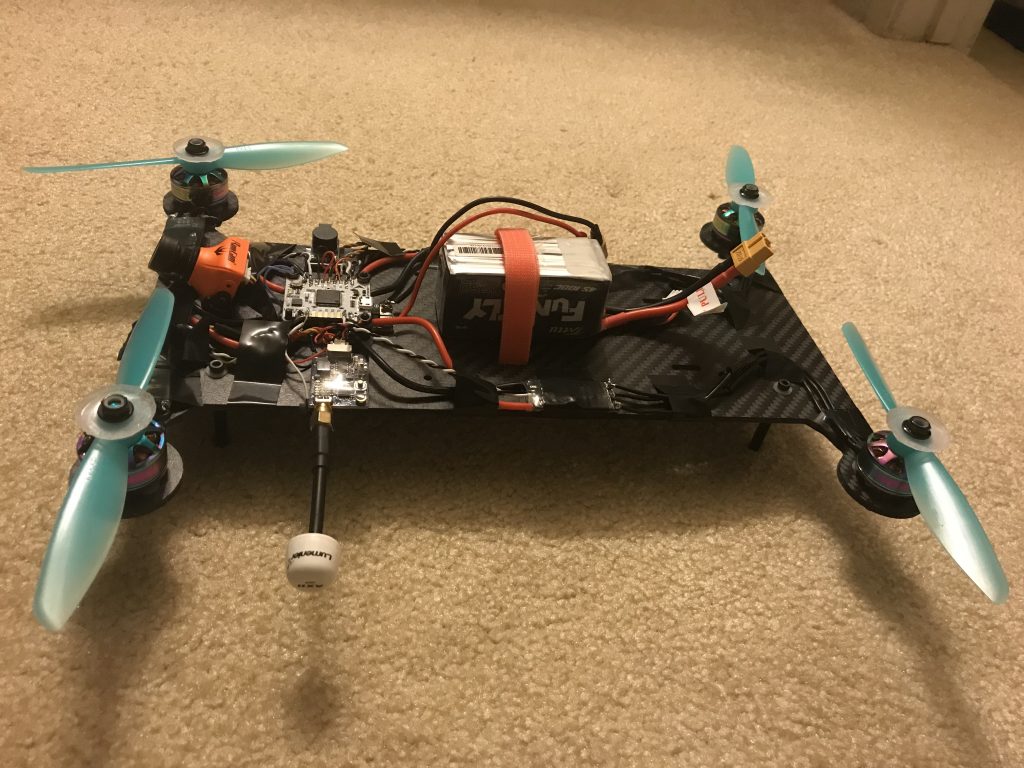
They actually work really well and are sorta stylish.
Maiden flight!
Programming
Ok, this might be clickbait because I didn’t write any code for this. However, I did have to do a lot of tuning with Betaflight to get this to take off. Joshua Bardwell’s YouTube channel is soooooo helpful.
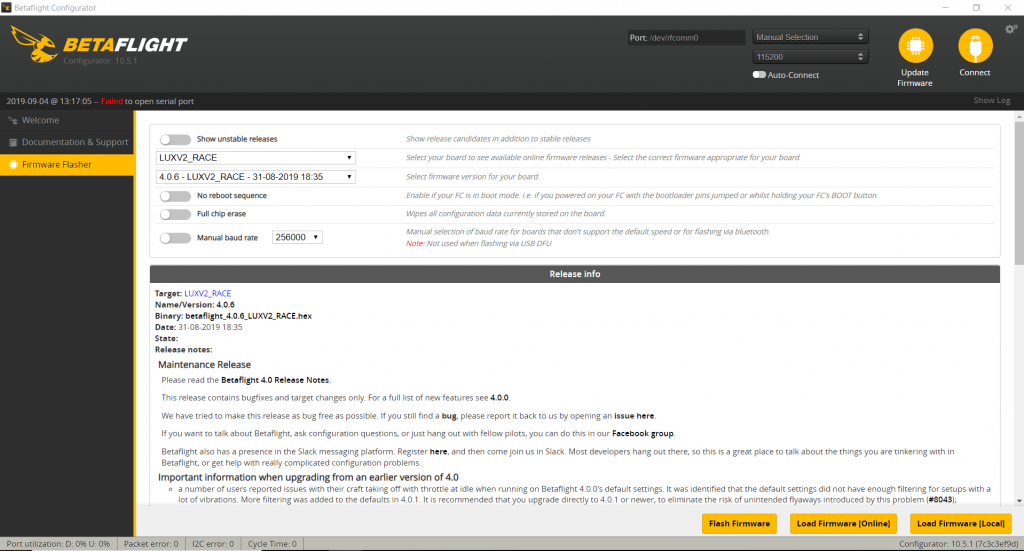
Betaflight was preloaded onto the Lux V2. This tricked me into thinking that I successfully flashed it to the latest version.
In reality, in order to do so, I needed to download a bunch of drivers onto my computer and do some weird USB rituals.
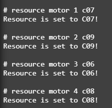
The most important thing that I needed to do with Betaflight was motor mapping. I needed to make sure that the motor orientation Betaflight expects matches what the flight controller determined.
Additionally, I needed to rotate the yaw angle by 90 degrees, add an arming switch, trim the min/max values for each channel, and reverse the direction of 3 motors (using Blheli_S).
Upcoming
- Adjust yaw settings
Reconfigure nichrome wire (maybe use leftover XT30)- Test and attach blowtorch
- Replace blowtorch with FAA friendly ketchup bottle
- Enable more switches for additional controls like buzzer or position hold
- Complete registration (FAA registration and HAM license)
Nichrome Wire
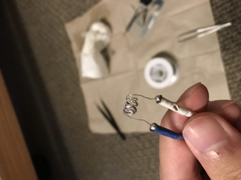
I managed to get a pretty nice coil of nichrome wire soldered to the ends of a brushed speed controller
And after connecting it to a small LiPo and a receiver, I can make the wire glow
